
Key Takeaways
- Rated fan airflow is not guaranteed installed airflow. A properly selected fan serving a pulse jet baghouse can deliver less than its catalog rating when the inlet or outlet duct creates unfavorable flow conditions.
- Elbows immediately beside the fan deserve special attention. Inlet swirl and nonuniform velocity can reduce impeller performance; outlet turbulence can prevent normal pressure recovery.
- Fan system effect is not just ordinary elbow friction. Add the extra installation-related effect to a complete pressure-loss review, using appropriate baghouse design calculators only for preliminary checks.
- Loaded filters move the operating point. Fan curves and the expected dirty-filter resistance must be considered together, not inferred from free-air CFM or motor power.
- Diagnose before replacing the fan. For broader weak suction and low airflow troubleshooting, first separate source-capture faults, duct restrictions, filter loading, and fan inlet/outlet effects. The laser cutting system layout guide illustrates why the complete extraction path matters.
Why a Dust Collector Fan Can Underperform After Installation
A centrifugal fan may pass its factory performance test, operate at the specified rotational speed, and draw a reasonable motor current—yet the dust collection hood still has weak suction. That does not automatically mean the fan is defective or too small.
In a laboratory rating arrangement, airflow approaches the fan under controlled conditions. In a real plant, the installation may include a sharp elbow immediately before the inlet, an abrupt rectangular-to-round transition, a damper, or an obstruction directly against the discharge. These features can produce distorted velocity profiles that make the installed fan behave differently from the published curve.
Dust collector performance begins at the pickup hood, continues through the duct network and filtration unit, and ends at the fan discharge or return-air arrangement. This article concentrates on the short duct sections immediately adjacent to the centrifugal fan—an issue that can be overlooked when engineers focus only on filter area or total duct length.
How Inlet Conditions Affect Centrifugal Fan Performance
Inlet Swirl and Uneven Impeller Loading
A centrifugal impeller is designed for a particular incoming flow pattern. A nearby elbow may deliver faster air to one side of the inlet and slower air to the other. Flow may rotate around the inlet axis, a condition commonly called inlet swirl or pre-rotation.
The direction of that rotation matters. Depending on its direction relative to the wheel, inlet swirl can change developed pressure, power demand, and the apparent operating curve. Nonuniform entry also loads different parts of the wheel unevenly, potentially increasing vibration and noise. A fan can therefore be mechanically sound but aerodynamically disadvantaged.
The location of an inlet elbow is more important than its presence somewhere in the building. An elbow several duct diameters away with adequate straight flow development is generally less disruptive than one connected directly to the fan flange. Actual spacing must follow the fan manufacturer’s installation guidance and the selected geometry; there is no universally safe straight-run length for every fan.
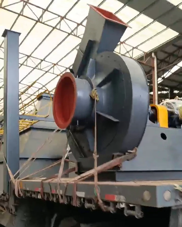
Inlet Boxes, Dampers, and Transitions
An undersized inlet duct, asymmetric inlet box, poorly shaped reducer, or inlet-vane damper can likewise create preferential flow or additional losses. Simply matching nominal flange diameters does not guarantee uniform entry. A transition should avoid unnecessary separation and abrupt changes in cross-section.
Turning vanes or straighteners may improve particular layouts, but adding them without evaluating pressure loss and maintenance requirements can create a new problem. In dust-handling ducts, any internal component must also be assessed for fouling, abrasion, and combustible-dust hazards.
What Happens at the Fan Outlet?
Outlet Velocity Profile and Pressure Recovery
Air leaving a centrifugal fan scroll is usually not evenly distributed across the outlet. An appropriate discharge duct provides space for the velocity profile to develop and for part of the kinetic energy to be recovered as static pressure.
A sharp elbow, blank wall, diffuser installed incorrectly, or immediate branch connection can disturb this process. Consequently, an outlet obstruction may make source suction seem inadequate even when the fan itself meets its test performance. A discharge elbow placed in an unfavorable direction relative to the fan wheel can make the loss worse.
Industry guidance describes an effective outlet duct length, but the required distance varies with velocity, fan configuration, duct geometry, and elbow direction. Published rules of thumb should be used only within their stated conditions, not treated as universal installation codes.
A Proper Connection Matters More Than a Bigger Motor
For a retrofit, compare the as-built discharge arrangement with the fan drawing. Is the outlet facing directly into a wall? Does the duct turn immediately? Is a silencer, backdraft damper, or transition installed much closer than shown in the fan selection? Could a gradual outlet section or properly arranged elbow remove the disturbance?
An outlet redesign may improve useful pressure without increasing fan speed. Conversely, an uncontrolled fan speed increase can raise power demand, noise, erosion, and mechanical loading while leaving the underlying geometry unchanged.
Fan System Effect Versus Ordinary Duct Pressure Loss
Every duct has normal resistance from wall friction and fittings. Fan system effect refers to additional performance loss caused by unfavorable airflow conditions at or near the fan that are not fully represented by ordinary fitting-loss calculations or the standard fan rating arrangement.
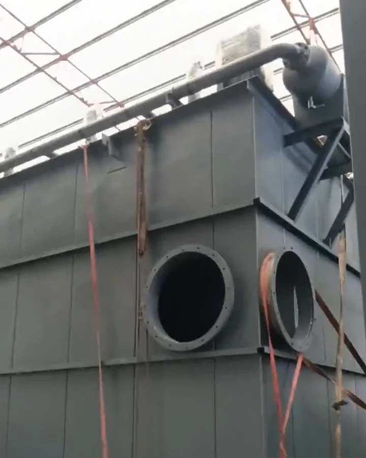
These effects can coexist. A tight elbow has its own frictional loss, and an elbow attached immediately to the fan inlet may also produce inlet distortion. If a design accounts for only the normal elbow coefficient, it may still overpredict actual installed airflow. Conversely, do not add an arbitrary large system-effect allowance when the fan manufacturer’s tested configuration already accounts for the specific installation.
| Installation feature | Ordinary loss or operating impact | Possible additional fan system effect |
|---|---|---|
| Long straight duct | Wall-friction pressure loss | Usually limited if flow is well developed |
| Elbow directly before inlet | Elbow resistance | Swirl and nonuniform impeller entry |
| Abrupt inlet transition | Local fitting loss | Asymmetric wheel loading |
| Elbow directly after outlet | Elbow resistance | Poor pressure recovery and distorted discharge profile |
| Silencer or damper near fan | Accessory pressure loss | Additional disturbance if geometry is unsuitable |
| Loaded filter bags or cartridges | Increased filter differential pressure | Primarily a system-curve change, not itself a fan system effect |
For technical selection, use the fan maker’s configuration-specific data and an applicable recognized fan-system method such as AMCA Publication 201. The objective is to estimate the actual system curve, including installation effects, before deciding whether a different fan or motor is necessary.
How Airflow, Static Pressure, and Fan Curves Fit Together
Airflow is expressed in CFM or m³/h. Static pressure describes pressure relative to the surrounding atmosphere at a location; pressure difference across individual components helps quantify their resistance. The fan must provide enough useful pressure to overcome hood entry, ducts, fittings, collectors, loaded filters, accessories, and the discharge path.
The operating point occurs where the installed system-resistance curve intersects the fan performance curve at the selected speed and air density. As filters load and resistance increases, a constant-speed fan may deliver less airflow. With clean filters, the opposite may happen. An engineered VFD control arrangement can maintain a target airflow within fan, motor, and system limits, but it cannot eliminate poor inlet geometry.
Consider a purely illustrative duct carrying 18,000 m³/h, equal to 5 m³/s. In a round duct of 0.60 m internal diameter, average velocity is about 17.7 m/s. At an assumed air density of 1.2 kg/m³, its velocity pressure is approximately 188 Pa. If a hypothetical fitting had a loss coefficient of 0.7 under the relevant convention, its basic estimated loss would be roughly 132 Pa. That arithmetic does not include any separate fan system-effect adjustment and is not a design recommendation. Actual coefficients, density, geometry, and flow measurements must be verified.
Diagnosing Weak Suction Without Guessing
Before replacing a fan, document whether the problem appeared immediately after installation, after a duct modification, or gradually as dust loading increased. This history is useful because poor inlet/outlet geometry often creates problems from commissioning, while filter blinding may change over time.
| Field observation | Likely checks | Evidence needed |
|---|---|---|
| Weak capture from first startup | Inlet/outlet arrangement, fan curve, speed, branch balancing | Actual airflow and static-pressure survey |
| Suction worsens as production continues | Filter loading, cleaning effectiveness, hopper discharge | Clean-to-loaded pressure trend at comparable airflow |
| New outlet duct preceded a performance drop | Elbow placement, transition, damper, discharge obstruction | Before/after drawings and pressure survey |
| Fan current seems normal but hood flow is low | System effect, blocked duct, wrong branch distribution | Fan speed, gas density, airflow traverses, fan curve |
| High vibration or unusual noise | Inlet swirl, impeller buildup, supports, bearing faults | Mechanical and aerodynamic inspection |
Do not rely on motor amperage as a direct airflow meter. Power response depends on fan type, speed, pressure and operating point. Likewise, filter differential pressure alone cannot establish fan performance. Qualified personnel should measure flow at suitable duct-traverse locations and compare fan inlet/outlet conditions with the manufacturer’s rating basis.
What Published Industrial Cases Teach Us
The following are third-party supplier or engineering-firm reports, not Omela customer projects. The reported measurements describe particular installations; they do not prove that every duct modification will produce the same results.
Factory Fan Met Its Duty, but the Outlet Layout Caused Weak Capture
A publicly documented service investigation at a bakery and thermal-processing equipment manufacturer in India involved an approximately 20 hp-class centrifugal blower, with an installation described around 7,500 m³/h and 280 mm water column. Operators reported inadequate suction at the pickup and initially suspected the fan.
The service team compared the installed machine against its factory test and reported that measured fan flow exceeded the specified design duty. The trouble was attributed to an abrupt obstruction against the fan discharge, with no appropriate outlet run or transition, together with a filter needing cleaning. The published recommendation was to change the outlet to a long-radius arrangement and move the filter-box connection.
Engineering lesson: verify the fan against its own performance data before replacing it. This report describes a diagnosis and recommended correction; it does not provide an independently measured post-modification airflow gain.
Paint Plant: Balancing More Than 60 Pickup Points
A Canadian paint-manufacturing application consolidated three collectors serving 39,360 CFM into a new central collection arrangement. According to the engineering provider’s report, the system included more than 60 pickup points, a 250 hp backward-inclined fan, and real-time airflow control that adjusted fan speed as filter resistance changed.
The contractor reported balanced capture and conveying velocities at the hoods, with no filter changes during the first year of operation. This is a system-integration result, not a controlled experiment isolating one fan elbow. It shows why source airflow, duct balancing, fan control, and loaded-filter conditions must be reviewed together.
Food-Processing Retrofit: Lower Discharge Resistance Preserved the Existing Fan
An engineering report on an existing 19,000 CFM food-product dust collection system described a change from outdoor exhaust to a filtered-air return configuration. The original arrangement had created building depressurization and condensation concerns. To manage the new return-air path, designers used larger downstream ductwork to reduce pressure loss and retained the existing fan.
The project also incorporated dust monitoring and fire/explosion isolation measures for the combustible material. The useful lesson is not that every return-air conversion is acceptable; it is that discharge-side pressure loss can determine whether an existing fan remains suitable. Any return-air arrangement requires appropriate hazard analysis, filtration verification, and regulatory review.
Installation and Commissioning Checklist
A reliable fan installation should be checked before production begins and again after the filters reach a representative operating condition:
- Verify the rating basis: Record the fan model, impeller type, speed, air density, fan curve, specified airflow, and intended pressure duty.
- Inspect the inlet: Check elbow distance and orientation, transitions, inlet boxes, dampers, obstructions, and adequate access for maintenance.
- Inspect the outlet: Review discharge direction, straight duct availability, nearby elbows, diffusers, silencers, dampers, and downstream equipment resistance.
- Measure the system: Establish flow, static pressures, filter differential pressure, fan current, speed, and vibration at documented operating conditions.
- Test representative loading: Confirm source capture with expected loaded-filter resistance, open branches, and normal production arrangements.
- Record corrections: Keep as-built drawings and test data so later duct modifications or filter changes can be evaluated against a real baseline.
For combustible dusts, changes to ducts, fan placement, return air, or internal flow devices must be reviewed through the applicable dust hazard analysis and protection strategy. Never bypass isolation devices or create uncontrolled dust releases to perform an airflow test.
Final Engineering Recommendation
The correct fan is not simply the one with the largest motor or highest catalog CFM. It is the fan that delivers the required flow against the installed system resistance, with acceptable noise, vibration, energy use, and safety margins.
Focus particularly on inlet swirl, discharge pressure recovery, and the additional system effect introduced by elbows and transitions near the fan. Confirm dirty-filter resistance and the full outlet path before replacing equipment. When discussing a new design or retrofit, provide the fan curve, duct arrangement, operating flow, pressure readings, filter-loading trend, and photographs of both fan connections. Those records make an engineering diagnosis far more dependable than a nameplate comparison.
FAQ
Why Does a Dust Collector Fan Deliver Less Airflow Than Its Rated CFM?
Catalog fan ratings are established under defined test conditions. In the plant, inlet swirl, immediate outlet elbows, additional duct resistance, dirty filters, or a different operating speed can shift performance. Measure actual flow and compare the installation with the rated fan configuration.
How Does an Elbow Near a Centrifugal Fan Inlet Affect Performance?
A nearby elbow can create uneven velocity and inlet swirl, changing how air enters the impeller. This may reduce developed pressure, alter power demand, and increase noise or vibration. The effect depends on elbow geometry, distance, and swirl direction.
What Is Fan System Effect in a Dust Collection System?
Fan system effect is the additional installed-performance loss caused by nonuniform or swirling airflow at or near the fan, beyond ordinary duct and fitting resistance. It should be evaluated with fan-specific data and appropriate engineering guidance, not guessed from motor size.
How Much Straight Duct Is Needed Before or After a Dust Collector Fan?
There is no universal length for every centrifugal fan. Required straight runs depend on fan type, duct velocity, inlet or outlet configuration, elbow direction, and manufacturer guidance. Evaluate the actual layout rather than applying a single rule without its stated conditions.
Should I Install a Larger Fan When Dust Collector Suction Is Weak?
Not before diagnosing the system. Verify source capture, duct restrictions, filter differential pressure, fan speed, inlet and outlet geometry, and measured airflow against the fan curve. Correcting an unfavorable connection or excessive resistance may restore performance without a larger fan.
Author

Jessica Ma – Senior Filtration Engineer, Omela Filtration
Jessica Ma is a senior filtration engineer at Omela Filtration, specializing in dust and liquid filtration. With over 15 years of experience, she focuses on optimizing baghouse performance, enhancing filtration efficiency, and developing high-performance solutions for industrial dust collectors and precision liquid filtration applications.