
Pre-Project Technical Support
- Review table size, enclosure, active zones, and open dampers
- Confirm materials, thickness range, laser power, and duty cycle
- Define outlet target, indoor/outdoor installation, and hazard data
A laser cutting dust collector is a source-capture filtration system engineered for the fine metal oxide fume and particulate generated by fiber laser, CO₂ laser, and related thermal cutting processes. It connects to the cutting table or enclosure through a zoned extraction duct and uses high-surface-area filter cartridges with automatic pulse cleaning.
Correct extraction protects operators and nearby equipment, limits visible haze, and helps prevent dust from interfering with cutting quality. Collector selection must be based on table size, open extraction zone, material and thickness, laser power, cutting duty, duct resistance, target airflow, required static pressure, and the fire or combustible-dust risk.
Smoke is captured below or around the cutting zone before it spreads into the workshop. The cutting-machine controller opens the damper for the active table zone, concentrating suction where the laser is working and reducing unnecessary airflow from inactive zones.
The fan must provide the required airflow at the total system resistance—not only at free-air conditions. Duct layout, damper position, table leakage, dirty-filter resistance, spark control, and final filtration all affect the operating point.
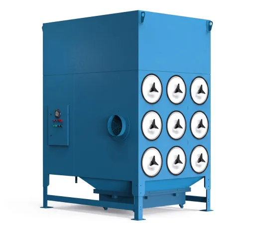
Zoned extraction, correctly selected fan duty, clean-on-demand pulse control, and quick-release cartridges help control energy, compressed-air use, downtime, and filter replacement cost.
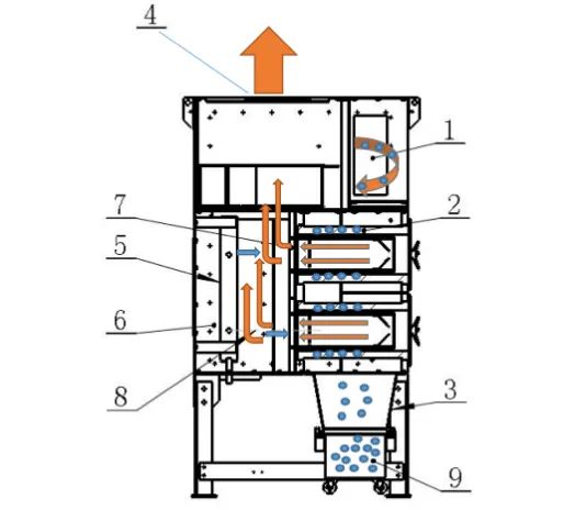
The complete system includes more than a collector cabinet. Effective laser-fume control starts at the cutting table, follows the active damper and duct network, protects the filters from hot debris, and maintains the required capture airflow as cartridge resistance changes. Controls can interlock the collector, fan, pulse system, alarms, and cutting machine.
High-surface-area cartridges and optional membrane media are selected for fine, dry metal oxide particulate and the required outlet target.
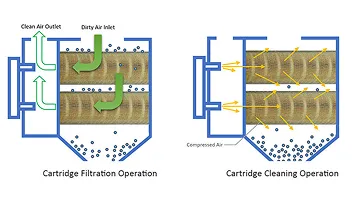
Timed or differential-pressure-controlled reverse pulses remove surface dust and help restore cartridge permeability during production.
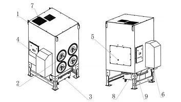
Side-access, independently removable cartridges reduce the time and clearance required for inspection and filter replacement.
The fan, pulse controller, differential-pressure sensor, temperature monitoring, alarms, and machine interlock can be integrated into one package.
Inlet baffles, drop-out zones, spark traps, temperature alarms, and other measures are selected from the actual ignition risk; no single device replaces a complete safety review.
Compact L/C configurations and higher-pressure A/B configurations support different table sizes, laser powers, duct layouts, and production duties.
Use these series as a preliminary selection guide. The final operating point must be checked against the cutting table, active extraction zones, duct losses, material, thickness, laser duty, and dirty-filter resistance.
| Series / Model | Fan Power | Max. Airflow | Static Pressure | Max. Inlet Velocity | Cartridges | Filter Area |
|---|---|---|---|---|---|---|
| A / OM-LC-4A | 5.5 kW | 5,800 m³/h | 2,800 Pa | 23 m/s | 4 × Ø350 × 660 mm | 80 m² |
| A / OM-LC-6A | 7.5 kW | 9,000 m³/h | 4,200 Pa | 35 m/s | 6 × Ø350 × 660 mm | 120 m² |
| A / OM-LC-8A | 11 kW | 11,000 m³/h | 5,000 Pa | 45 m/s | 8 × Ø350 × 660 mm | 160 m² |
| A / OM-LC-12A | 15 kW | 13,000 m³/h | 5,300 Pa | 52 m/s | 12 × Ø350 × 660 mm | 240 m² |
| A / OM-LC-18A | 18.5 kW | 15,000 m³/h | 5,600 Pa | 55 m/s | 18 × Ø350 × 660 mm | 360 m² |
| B / OM-LC-4B | 4 kW | 5,800 m³/h | 2,800 Pa | 23 m/s | 4 × Ø350 × 660 mm | 80 m² |
| B / OM-LC-6B | 5.5 kW | 6,600 m³/h | 3,300 Pa | 26 m/s | 6 × Ø350 × 660 mm | 120 m² |
| B / OM-LC-8B | 7.5 kW | 8,800 m³/h | 4,100 Pa | 33 m/s | 8 × Ø350 × 660 mm | 160 m² |
| B / OM-LC-12B | 11 kW | 10,800 m³/h | 5,900 Pa | 42 m/s | 12 × Ø350 × 660 mm | 240 m² |
| B / OM-LC-18B | 15 kW | 12,800 m³/h | 5,200 Pa | 50 m/s | 18 × Ø350 × 660 mm | 360 m² |
| L / OM-LC-2L | 1.5 kW | Custom | Custom | To confirm | 4 × Ø300 × 660 mm | To confirm |
| L / OM-LC-4L | 2.2 kW | 4,600 m³/h | 2,000 Pa | 28 m/s | 4 × Ø200 × 400 mm | 50 m² |
| C / OM-LC-4C | 3 kW | 5,200 m³/h | 2,300 Pa | 30 m/s | 4 × Ø300 × 660 mm | 70 m² |
| C / OM-LC-6C | 4 kW | 6,000 m³/h | 2,900 Pa | 33 m/s | 6 × Ø300 × 660 mm | 100 m² |
| Model | Noise | Dust Bin | Max. Weight | Inlet | Dimensions (L × W × H) | Reference Machine Range |
|---|---|---|---|---|---|---|
| OM-LC-4A / 4B | 73 ±2 dB | 50 L | 460 kg | Ø300 mm | 1,162 × 1,261 × 2,152 mm | 1.5 × 3 m / 2 × 4 m class, ≤12 kW |
| OM-LC-6A | 75 ±2 dB | 70 L | 690 kg | Ø300 mm | 1,602 × 1,346 × 2,153 mm | 2 × 6 m / 2.5 × 6 m class, ≤20 kW |
| OM-LC-6B | 75 ±2 dB | 70 L | 660 kg | Ø300 mm | 1,602 × 1,346 × 2,153 mm | 2 × 6 m / 2.5 × 6 m class, ≤20 kW |
| OM-LC-8A / 8B | 78 ±2 dB | 90 L | 870 / 820 kg | Ø350 mm | 1,162 × 2,126 × 2,195 mm | 3 × 12 m class, ≤30 kW |
| OM-LC-12A / 12B | 80 ±2 dB | 160 L | 1,380 / 1,320 kg | Ø350 mm | 1,607 × 2,166 × 2,235 mm | Large-format / above 30 kW class |
| OM-LC-18A / 18B | 85 ±2 dB | 160 L | 1,590 / 1,520 kg | Ø350 mm | 1,607 × 2,166 × 2,750 mm | Ultra-high-power, large-format systems |
| OM-LC-2L | To confirm | To confirm | To confirm | Ø250 mm | 859 × 730 × 1,159 mm | Custom compact system; confirm application |
| OM-LC-4L | ≤72 ±2 dB | 40 L | 280 kg | Ø250 mm | 947 × 830 × 1,650 mm | Compact laser systems, ≤3 kW class |
| OM-LC-4C | 73 ±2 dB | 50 L | 340 kg | Ø250 mm | 1,079 × 830 × 1,959 mm | 1.5 × 3 m / 2 × 4 m class, ≤6 kW |
| OM-LC-6C | ≤75 ±2 dB | 70 L | 490 kg | Ø300 mm | 1,429 × 830 × 2,050 mm | 2 × 6 m / 2.5 × 6 m class, ≤12 kW |
Laser-fume loading changes with material, thickness, assist gas, cutting speed, laser power, table size, and production duty. Omela configures the extraction zone, duct system, fan, cartridges, controls, and safety interfaces around the actual cutting process.



Differential-pressure trends indicate cartridge loading and can trigger pulse cleaning or maintenance alarms.
A variable-frequency drive can maintain the required extraction point as dampers switch and filter resistance changes.
The control target is adequate capture at the active zone—not the highest possible free-air volume. Excess airflow can waste energy, increase noise, and load filters unnecessarily.
This design example shows a collector selected for a medium-to-large fiber laser cutting table with zoned extraction. The operating challenge is to capture fine metal fume at the active cutting zone while overcoming the pressure loss of the table, dampers, ductwork, spark-control stage, filter cartridges, and outlet system.
The following parameters illustrate a preliminary OM-LC-6A reference configuration. Final selection requires the cutting-machine and duct data.
| Application | Flatbed fiber laser cutting fume extraction |
| System Type | Pulse-cleaned cartridge collector with zoned table extraction |
| Designed Airflow | 9,000 m³/h reference maximum |
| Reference Static Pressure | 4,200 Pa |
| Reference Cutting Table | 2 × 6 m or 2.5 × 6 m class; application review required |
| Filter Media | Application-matched F9/H13 cartridge option; final media to be confirmed |
| Cartridge Quantity | 6 quick-release cartridges |
| Cartridge Size | Ø350 × 660 mm |
| Total Filter Area | 120 m² nominal reference area |
| Dust Bin Capacity | 70 L |
| Cleaning Control | Automatic pulse cleaning with differential-pressure monitoring |
| Spark Control | Inlet spark-control stage selected from the material and hazard review |
| Power Supply | 380 V / 50 Hz |
A model should not be selected from laser power alone. Confirm the active extraction-zone area, open dampers, table leakage, duct diameter and length, elbows, material mix, plate thickness, and cutting duty.
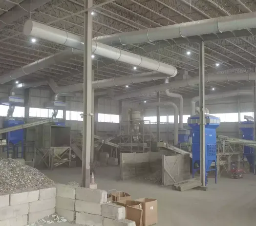
6×
Quick-Release Cartridges
Six independently removable cartridges provide 120 m² of nominal reference media area while simplifying inspection and replacement access.
| Fan Power | 7.5 kW |
| Fan Airflow Range | Up to 9,000 m³/h |
| Reference Static Pressure | 4,200 Pa |
| Maximum Inlet Velocity | 35 m/s reference |
| Motor / Electrical | 380 V / 50 Hz; final motor and area classification to be confirmed |
| Control Cabinet | Machine start/stop interlock, differential-pressure monitoring, pulse control, temperature alarm, and optional VFD. |
Start with the table dimensions, enclosure condition, extraction-zone geometry, number of dampers open at once, and leakage around slats and access doors. These determine the capture airflow required at the cutting source.
Carbon steel, stainless steel, coated material, aluminum, and other alloys produce different fume and hazard profiles. Plate thickness, laser power, assist gas, cutting speed, pierce frequency, and simultaneous machine operation affect loading.
Select the fan from the required airflow at total resistance: table, dampers, duct, elbows, spark-control device, loaded cartridges, final filter, and outlet. Free-air fan volume does not represent the installed operating point.
Match cartridge grade and surface treatment to fine metal fume, humidity, temperature, and outlet target. Verify nominal media area, effective pleat use, pulse pressure, clean compressed-air quality, and differential-pressure setpoints.
Evaluate hot particles, combustible metal dust, mixed materials, oil or coating contamination, and possible ignition sources. Flame-retardant media or a spark trap alone does not make a system safe; protection, isolation, collector placement, dust disposal, and indoor air recirculation require a qualified hazard review.
From cutting-table data and duct design to fan verification, commissioning, cartridge replacement, and troubleshooting.

A laser cutting collector must work with the cutting table, dampers, duct network, fan curve, filter loading, controls, and safety strategy as one system. Omela reviews the operating data and documents the proposed configuration instead of selecting equipment from laser power alone.
Media grade, surface treatment, cartridge size, pleat construction, gasket, and flame or static properties are reviewed against the metal fume, humidity, temperature, cleaning system, and outlet target.
The proposed airflow is checked against cutting-table loss, active dampers, ductwork, spark control, loaded cartridges, and outlet components so the fan is selected for the installed operating point.
Available functions include machine start/stop interlock, damper sequencing, differential-pressure pulse control, temperature and fault alarms, dust-bin reminders, and VFD airflow adjustment.
Quick-release cartridges, front or side access, removable dust bins, visible controls, and planned service clearance reduce routine inspection and replacement effort.
Support can cover preliminary selection, drawing review, installation guidance, commissioning baselines, pulse and airflow optimization, replacement cartridges, and troubleshooting throughout the collector lifecycle.






It is a source-capture system that removes fine metal fume and particulate from a laser cutting table or enclosure using ducted extraction, filter cartridges, a fan, controls, and dust collection equipment.
Cleanable units commonly use short compressed-air pulses to release dust from the cartridge surface into a hopper or removable bin.
Sizing starts with the capture airflow required at the active cutting zone and the static pressure needed to overcome the complete extraction path.
Selecting by laser power alone can result in weak table capture, unnecessary energy use, or unstable filter loading.
There is no universal airflow value. The requirement depends on:
Provide the table drawing and damper logic so airflow can be calculated from the actual extraction geometry.
Airflow determines capture at the source, while static pressure determines whether the fan can maintain that airflow through the installed system. Resistance includes:
A collector with a high free-air rating may still provide weak capture if its fan cannot overcome the system resistance.
Media selection depends on particle size, material chemistry, temperature, humidity, dust release, required outlet level, and ignition risk.
Filter grade alone does not determine complete-system emissions; cartridge sealing, airflow, pulse cleaning, and housing integrity also matter.
The pulse system needs stable, clean, dry compressed air at the pressure and flow specified for the collector. Oil, water, or inadequate supply can cause:
Confirm the connection size, operating pressure, air consumption per pulse, dryer performance, and available flow while other plant equipment is operating.
Higher power can increase fume generation, especially with thick plate and intensive piercing, but laser power is only one input. Also consider:
A smaller well-sealed zone may need less airflow than a larger leaking table even when its laser power is higher.
Thermal cutting generates very fine metal oxide particulate that can remain airborne, penetrate the breathing zone, settle on electronics, and load filter media rapidly. Design risks include:
The capture hood, spark control, cartridge media, sealing, cleaning, and dust disposal must be engineered as one system.
The cutting table is divided into extraction sections. The machine controller opens the damper nearest the cutting head so suction is concentrated beneath the active area.
Poor damper operation or excessive leakage can cause smoke escape even when the collector itself is correctly sized.
Published reference systems commonly state high collection efficiencies, but the number is meaningful only when particle size, test method, filter grade, airflow, and whether the value applies to media or the complete collector are identified.
Final outlet performance depends on cartridge media, gasket sealing, housing leakage, pulse cleaning, operating airflow, maintenance condition, and any secondary filter.
Differential pressure represents the resistance to airflow across the filter media.
Stable DP reflects balanced airflow and effective cleaning.
A controller opens diaphragm valves in sequence and releases short bursts of compressed air into the cartridges. The pressure wave dislodges surface dust into the collection bin. Cleaning can operate as:
Evaluate the material, dust test data, mixed-metal risk, oil or coating contamination, collector location, isolation, fire protection, dust disposal, and applicable local requirements.
Measure airflow and static pressure at defined points before replacing the fan or cartridges.
Do not use a universal calendar interval. Review differential-pressure trends, outlet emissions, physical damage, gasket condition, loss of cleanability, operating hours, and material history.
Replace cartridges as a matched set when uneven resistance would disturb airflow, and investigate the cause of premature loading before installing new elements.
Do not assume that mixed-metal collection is acceptable. Aluminum and some other metal dusts can present significant fire or explosion hazards, and mixing materials may change the risk. A qualified review should address:
Zoned extraction and clean-on-demand control can reduce unnecessary airflow and pulse cycles when correctly commissioned.
Yes. Many performance issues can be resolved through:
Start with measured airflow, static pressure, DP trends, damper operation, and a process review to identify the actual constraint before purchasing replacement equipment.
Send the cutting-table drawing, active-zone dimensions, material and thickness range, laser power, production duty, duct layout, outlet target, and available compressed air. Omela will prepare a preliminary airflow and collector selection.