
Pre-Project Technical Support
- Review airflow, temperature, pressure, and operating range
- Confirm particle distribution, density, loading, and flowability
- Define outlet target, product recovery, installation, and hazard data
An industrial cyclone dust collector is a dry mechanical separator that removes particulate from an air or process-gas stream without filter bags or cartridges. It is commonly used as a product receiver, an independent collector for coarse material, or a pre-cleaner ahead of a baghouse, cartridge collector, scrubber, or other final filtration stage.
A cyclone is especially useful for high dust loading, abrasive particles, elevated temperatures, and recoverable bulk material. Its performance is not a single fixed percentage: particle size distribution, particle density, gas density, cyclone geometry, inlet velocity, pressure drop, air leakage, and dust discharge all affect the grade-efficiency curve.
Dust-laden gas enters the cylindrical body through a tangential or engineered inlet. The inlet converts linear airflow into a rotating outer vortex, creating centrifugal force that drives particles toward the wall.
An airtight rotary airlock, double-dump valve, or sealed collection container is normally used at the hopper outlet. Uncontrolled air leakage at the discharge can disturb the vortex, re-entrain collected dust, and reduce separation performance.
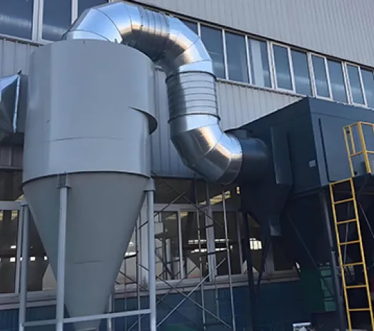
Removing coarse and heavy particulate before the final collector can reduce filter loading, cleaning demand, abrasion, product loss, and unplanned maintenance across the complete system.
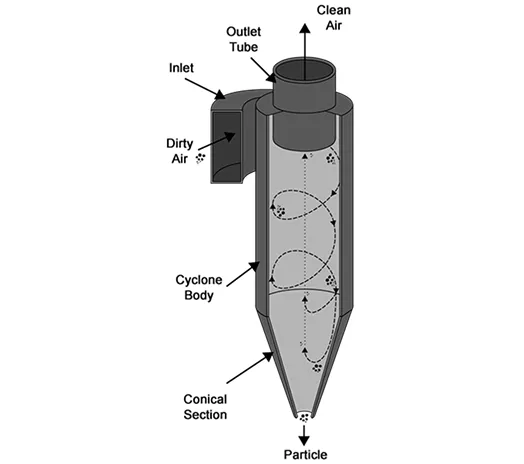
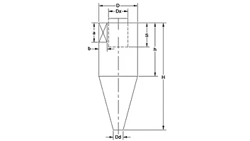
A reliable cyclone is more than a cone-shaped vessel. The inlet, body proportions, vortex finder, cone length, hopper, discharge seal, fan duty, duct transitions, and wear protection must be engineered as one aerodynamic system. Small geometry changes can alter both cut point and pressure loss.
Mechanical separation eliminates routine filter-media replacement and compressed-air pulse cleaning, simplifying service and consumable planning.
The open internal passage can process high inlet concentrations and continuously discharge separated bulk material when the hopper seal is maintained.
With suitable shell material, refractory, expansion allowance, and downstream equipment, cyclones can serve hotter gas streams than standard filter media.
Replaceable AR plate, ceramic, basalt, or other wear protection can be concentrated at the inlet, barrel, cone, and other high-velocity impact zones.
Dry captured material can be returned to the process or collected separately, while downstream bags or cartridges receive a lower coarse-particle burden.
A single large cyclone favors capacity and simplicity; parallel smaller-diameter cyclones can improve fine-particle separation while serving higher total airflow.
There is no universal cyclone model for every dust. Use the configuration comparison below to define the duty, then verify geometry and fan performance from representative particle and gas data.
| Configuration | Primary Duty | Particle / Loading Profile | Efficiency–Pressure Trade-off | Typical Arrangement | Main Advantage | Important Limitation |
|---|---|---|---|---|---|---|
| General-Purpose Single Cyclone | Coarse dust collection or product recovery | Coarse, dense, dry, free-flowing material | Lower resistance; moderate fine-particle capture | One cylindrical-conical separator | Simple, economical, easy to inspect | Fine respirable dust usually requires an afterfilter |
| High-Efficiency Single Cyclone | Smaller cut size where extra pressure is available | Medium-to-coarse particulate with stable properties | Higher separation potential with higher pressure loss | Optimized inlet, body, cone, and vortex finder | Better grade efficiency than a general-purpose design | More sensitive to wear, leakage, and off-design flow |
| Multi-Cyclone Array | High total airflow with smaller cyclone diameters | Consistent dry dust distributed across cells | Improved fine fraction capture; distribution loss must be checked | Parallel cyclone tubes with common plenum and hopper | Scalable capacity and smaller effective cut size | Uneven flow or blocked cells reduce performance |
| Heavy-Duty Abrasion-Resistant Cyclone | Mining, cement, foundry, blasting, and mineral duty | High loading, dense and abrasive particles | Geometry balances separation, erosion, and fan power | Thick shell with replaceable wear liners | Longer service life in severe duty | Wear zones and liner joints require planned inspection |
| High-Temperature / Corrosion-Resistant Cyclone | Hot or chemically aggressive process gas | Temperature or chemistry beyond standard carbon-steel duty | Performance depends on actual gas density and expansion | Alloy, stainless, coated, refractory-, or ceramic-lined construction | No heat-sensitive filter media inside the cyclone | Downstream fan, airlock, seals, and afterfilter must share the duty rating |
| Cyclone + Final Filter | Bulk pre-separation followed by fine-dust control | Mixed coarse and fine distribution or strict outlet target | Cyclone pressure loss is added to total system resistance | Cyclone upstream of baghouse, cartridge collector, or scrubber | Protects final filters and stabilizes loading | Must verify fan margin, ignition isolation, and dust discharge at both stages |
The airflow values below correspond to reference inlet velocities of 12, 15, and 18 m/s. Pressure drop must be calculated from the selected model, actual gas conditions, inlet velocity, duct arrangement, and complete system resistance.
Swipe horizontally to view all model specifications.
| Model | Flow Range (m³/h) | Airflow @ 12 m/s (m³/h) | Airflow @ 15 m/s (m³/h) | Airflow @ 18 m/s (m³/h) | Dimensions (Φ × L mm) | Weight (X / Y Type kg) |
|---|---|---|---|---|---|---|
| OM-CY-5.5 | 1,000–1,500 | 1,000 | 1,200 | 1,500 | Φ552 × 950 | 94 / 84 |
| OM-CY-7.5 | 2,000–3,000 | 2,000 | 2,500 | 3,000 | Φ762 × 1,360 | 161 / 145 |
| OM-CY-9.6 | 3,000–4,500 | 3,000 | 3,800 | 4,500 | Φ996 × 1,640 | 262 / 235 |
| OM-CY-11 | 4,000–6,000 | 4,000 | 5,000 | 6,000 | Φ1,110 × 1,880 | 341 / 310 |
| OM-CY-12 | 4,900–7,300 | 4,900 | 6,100 | 7,300 | Φ1,230 × 2,090 | 416 / 376 |
| OM-CY-13 | 5,700–8,600 | 5,700 | 7,100 | 8,600 | Φ1,330 × 2,225 | 497 / 447 |
| OM-CY-14 | 6,700–10,100 | 6,700 | 8,400 | 10,100 | Φ1,445 × 2,420 | 568 / 512 |
| OM-CY-15 | 8,300–12,500 | 8,300 | 10,400 | 12,500 | Φ1,599 × 2,685 | 697 / 617 |
| OM-CY-16 | 10,000–15,200 | 10,000 | 12,600 | 15,200 | Φ1,765 × 2,950 | 840 / 765 |
| OM-CY-17 | 11,500–17,200 | 11,500 | 15,200 | 17,200 | Φ1,890 × 3,165 | 989 / 903 |
| Design Input | Minimum Data | Why It Matters | Design Check |
|---|---|---|---|
| Gas Flow | Normal, minimum, maximum, actual temperature and pressure | Sets cyclone diameter or number of parallel cells | Inlet velocity and pressure drop across the full operating range |
| Dust Distribution | Representative particle-size distribution, not only average size | Defines grade efficiency and expected carryover | d50 cut point and collection by particle-size band |
| Dust Properties | Bulk and true density, loading, shape, adhesion, moisture, chemistry | Affects inertia, flowability, corrosion, build-up, and recovery | Hopper angle, material, coating, and discharge method |
| Process Conditions | Temperature, humidity, pressure, gas composition, upset cases | Changes gas density and construction requirements | Thermal expansion, corrosion allowance, seals, and insulation |
| Installation | Duct sizes, elevation, available height, support loads, fan curve | Determines real operating point and mechanical arrangement | Total static pressure, access, structure, wind, and seismic loads |
| Safety Basis | Combustibility data, ignition sources, location, and local code | A cyclone does not eliminate fire or explosion risk | Grounding, detection, venting/suppression, isolation, and safe discharge |
Cyclone performance changes with particle size and density, inlet loading, gas properties, airflow, pressure drop, geometry, and discharge sealing. Omela configures the separator, wear protection, ductwork, fan, hopper, airlock, and final filtration around the actual process duty.



The cut point describes the particle size collected at 50% grade efficiency and is more useful than an unsupported overall-efficiency claim.
Inlet velocity must remain high enough to form a stable vortex but not so high that fan energy, abrasion, and pressure loss become excessive.
The design target is the required grade efficiency at the real gas flow—not the highest possible inlet velocity. Every gain in separation must be evaluated against pressure drop, fan power, wear, and particle re-entrainment.
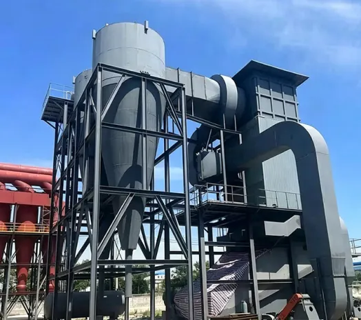
This design example shows how a cyclone can protect a downstream fabric or cartridge collector handling a high-load mineral process. The operating challenge is to remove the coarse, dense, and abrasive fraction without creating excessive pressure loss, wall erosion, hopper build-up, or air leakage at the dust discharge.
The following parameters illustrate a preliminary engineering basis, not a guaranteed model schedule. Final selection requires representative dust and gas data plus the installed fan curve.
| Application | High-load abrasive mineral dust pre-separation |
| System Type | Heavy-duty dry cyclone upstream of a final fabric or cartridge collector |
| Designed Airflow | To be calculated from the process exhaust and full operating range |
| Inlet Dust Loading | High and variable; define normal, peak, and upset conditions |
| Target Duty | Remove bulk coarse particulate and reduce loading on the downstream collector |
| Particle Data | Full size distribution, true density, bulk density, shape, moisture, and abrasiveness required |
| Construction | Carbon steel, stainless steel, or alloy selected from temperature and corrosion duty |
| Wear Protection | Replaceable liner or wear plate at inlet and other predicted impact zones |
| Discharge System | Rotary airlock, double-dump valve, or sealed receiver sized for bulk discharge rate |
| Final Filtration | Baghouse, cartridge collector, or other stage selected for the remaining fine fraction |
| Performance Basis | Grade-efficiency curve, cut point, and cyclone pressure loss at defined gas conditions |
| Safety Basis | Dust combustibility, ignition sources, isolation, explosion protection, and safe material handling |
| Installation Data | Available height, duct orientation, access, structure, wind/seismic loads, and downstream fan curve |
A cyclone should not be selected from airflow alone. Confirm particle-size distribution, density, loading, gas temperature and pressure, inlet velocity, allowable pressure drop, discharge sealing, and outlet target.
0×
Filter Elements Inside
Separation is produced by aerodynamic forces rather than filter elements. Routine attention shifts to wear, build-up, air leakage, hopper discharge, and the downstream final collector.
| Operating Airflow | Verify normal, minimum, maximum, and upset conditions |
| Inlet Velocity | Maintain the engineered range at every operating point |
| Cyclone Pressure Loss | Add the predicted value to duct and downstream equipment resistance |
| Grade Efficiency / d50 | State against the submitted particle distribution and gas density |
| Hopper & Airlock | Size for peak solids rate and preserve the pressure seal |
| Inspection Plan | Baseline wall thickness; inspect inlet, cone, liner joints, seals, and carryover trend. |
Start with a representative particle-size distribution, not only an average size. Add true and bulk density, inlet concentration, shape, moisture, adhesion, and peak solids rate to predict separation and hopper duty.
Define actual and normal flow at minimum, design, and maximum production. Temperature, pressure, humidity, and gas composition change gas density, cyclone velocity, material selection, thermal expansion, and downstream equipment duty.
Define the required grade-efficiency curve or cut point and the allowable pressure loss. A smaller outlet or higher velocity may improve separation but also increases fan power, wear, and sensitivity to off-design flow.
Match shell and liner construction to abrasion, corrosion, and temperature. Size the cone, hopper, airlock, or double-dump valve for the peak solids rate, and prevent false air from entering through the discharge or access doors.
Confirm whether a baghouse, cartridge collector, scrubber, or HEPA stage is needed for fine carryover and the outlet target. For combustible dust, the cyclone, airlock, ducting, downstream collector, isolation, protection, grounding, placement, and dust disposal must be reviewed as one hazard-control system.
From dust characterization and aerodynamic sizing to wear protection, commissioning, inspection, and retrofit support.
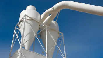
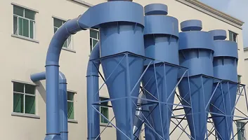
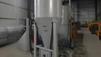
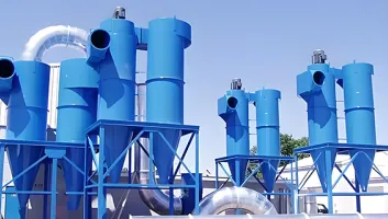
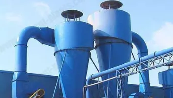
A cyclone must work with the source, duct network, fan curve, dust discharge, downstream collector, and safety strategy as one system. Omela reviews the particle and process data and documents the selection basis instead of assigning a model from airflow alone.
Inlet, barrel, cone, vortex finder, and dust outlet proportions are selected against the airflow range, particle distribution and density, loading, pressure budget, and required grade efficiency.
The proposed airflow is checked against source capture, ductwork, cyclone pressure loss, downstream filtration, and outlet components so the fan is selected for the real installed operating point.
Carbon steel, stainless steel, alloys, refractory, ceramic, basalt, and replaceable wear plate options are reviewed against abrasion, temperature, corrosion, impact velocity, and maintenance access.
Inspection doors, replaceable wear sections, accessible liner joints, removable cone options, hopper-level provisions, and service clearance help simplify inspection and planned repair.
Support can cover preliminary sizing, drawing review, fan and duct checks, installation guidance, commissioning baselines, wear monitoring, airlock checks, retrofit work, and troubleshooting.






It is a dry mechanical separator that uses a rotating gas flow and centrifugal force to remove particles without internal filter bags or cartridges.
It can operate as a coarse-dust collector, a product receiver, or a pre-separator ahead of final filtration.
Sizing starts with the actual gas flow and particle-size distribution, then checks the grade-efficiency target and available pressure drop.
Selecting by airflow alone can result in excess carryover, unnecessary fan energy, rapid wear, or unstable operation.
There is no universal minimum particle size. Collection depends on:
Cyclones usually favor coarse and dense particles. Fine respirable material generally needs a downstream baghouse, cartridge collector, scrubber, or other final stage.
The d50 cut point is the particle size collected at 50% grade efficiency. A grade-efficiency curve shows collection at each particle-size band and is more informative than one overall percentage.
Final selection should use the expected carryover by particle size, not a marketing percentage alone.
Pressure drop represents the energy used to create and maintain the rotating flow. Higher inlet velocity or more aggressive geometry can improve separation within limits, but it also increases fan power and abrasion.
Check cyclone loss together with ducts, dampers, downstream filters, silencers, stacks, and dirty-system allowance.
A single large cyclone offers simple construction and high capacity. A multi-cyclone divides the flow among several smaller-diameter cells, which can improve separation of a finer fraction for the same total airflow.
The better choice depends on particle data, pressure budget, available height, maintenance access, and allowable carryover.
Add a cyclone upstream when coarse or heavy material is overloading, abrading, or rapidly blinding the final collector. Common indicators include:
Verify that the existing fan has enough static-pressure margin for the added cyclone and that safety isolation covers both separation stages.
Sometimes it can collect coarse process material independently, but it normally cannot replace final filtration where fine, respirable, toxic, or regulated particulate is present.
Use a cyclone for bulk separation and size the final collector for the remaining particle-size distribution and loading.
Yes, if every component is designed for the actual continuous and upset temperatures. The cyclone itself contains no heat-sensitive filter media, but the complete system still requires engineering checks.
If an afterfilter follows the cyclone, cool or condition the gas to remain safely inside that filter's rated limits.
Identify high-velocity impact zones through experience, inspection history, or flow analysis. Use appropriate shell thickness and replaceable AR plate, ceramic, basalt, or other compatible lining where justified.
Establish baseline wall thickness and inspect the inlet, barrel, cone, vortex finder, liner joints, and elbows. Do not wait for external dust leakage to reveal wear-through.
The cyclone relies on a stable pressure field and vortex. Air drawn through an open hopper, leaking drum, worn rotary valve, or poor access-door seal can re-entrain collected dust and increase carryover.
A good cyclone with a poor discharge seal can perform like a badly selected cyclone.
These materials need special review. Moisture, condensation, tacky coatings, or interlocking fibers can build up on the inlet, wall, cone, or hopper and disturb the vortex or bridge over the discharge.
Use representative dust test data and a qualified hazard assessment to address grounding and bonding, ignition control, venting or suppression, isolation, placement, housekeeping, and safe dust disposal under applicable local requirements.
Measure flow and cyclone pressure loss, inspect the internals and discharge, and compare current dust data with the original selection basis.
Cyclones have no filter elements to replace, but they are not maintenance-free. Inspection frequency should reflect abrasion, corrosion, temperature, duty hours, and failure consequence.
Inspect wall thickness, wear liners, inlet, vortex finder, cone, welds, access seals, supports, hopper level, airlock clearances, fan condition, pressure loss, and downstream carryover trend.
It may, but verify every product and operating point. Changes in density, size distribution, moisture, loading, gas flow, or temperature can shift the cut point and discharge behavior. Review:
The lowest purchase price is not always the lowest lifecycle cost; excessive pressure drop or rapid wear can outweigh initial savings.
Often yes. A cyclone can be installed upstream to reduce bulk loading, but the retrofit must be checked as a system:
Start with measured airflow and static pressure plus representative dust data before purchasing equipment or changing the fan.
Send the gas-flow range, temperature and pressure, particle-size distribution, dust density and loading, moisture, abrasiveness, duct layout, available pressure, discharge method, and outlet target. Omela will prepare a preliminary cyclone selection.