
Key Takeaways
- A laser cutting dust collector should be laid out as one airflow system: cutting table → active damper → ductwork → spark control → filter cartridges → fan → exhaust, with collected dust discharged separately through the hopper or dust bin.
- Cartridge dust collectors are commonly used for laser fume because pleated cartridges provide large filtration area in a compact footprint, but their location must still allow short duct runs, pulse-cleaning access, cartridge replacement, and dust-bin maintenance.
- Good source capture starts at the cutting table. A zoned downdraft table usually performs better than pulling maximum airflow through the entire bed at once.
- Fan selection should be based on required airflow at total installed static pressure, including table loss, dampers, ducts, elbows, spark-control devices, loaded cartridges, final filters, and the exhaust path.
- Spark and hot-particle control should be positioned before the filter cartridges, not added only after cartridge burn damage appears.
- The shortest possible duct is not always the only objective. Layout should balance airflow resistance, dust transport, spark control, collector location, maintenance access, noise, exhaust routing, and workshop floor space.
Think of the System as One Airflow Path
A laser cutting dust collector should not be laid out as several independent pieces of equipment.
The system works as a chain:
Cutting Table → Active Extraction Zone → Damper → Ductwork → Spark Control → Cartridge Collector → Fan → Exhaust
At the same time, captured solids follow a second path:
Filter Surface → Pulse Cleaning → Hopper → Dust Bin / Drum → Disposal
Both paths matter.
If table capture is poor, smoke escapes before the collector can help.
If duct resistance is underestimated, the fan cannot maintain the required airflow.
If hot particles travel directly into the collector, cartridges may suffer burn damage.
If the dust bin is difficult to access, collected material may remain in the hopper too long.
A successful layout therefore connects capture, transport, filtration, fan performance, and maintenance.
Main Components and Their Layout Function
| System Part | Main Function | Typical Layout Concern |
|---|---|---|
| Cutting table / active zone | Capture fume at source | Zoning, leakage, open area |
| Ductwork | Transport contaminated air | Diameter, length, elbows, settling |
| Spark-control stage | Reduce hot debris before filters | Location and pressure loss |
| Cartridge collector | Capture fine metal fume | Filter area and service access |
| Fan | Maintain required airflow | Total static pressure |
| Exhaust | Discharge clean air | Indoor return or outdoor route |
| Hopper / dust bin | Receive pulse-cleaned dust | Access and disposal frequency |
The collector cabinet is therefore only one part of the layout.
Cutting Table Capture Comes First
For flatbed fiber laser cutting, the table is normally the real starting point of the dust collection design.
A large table does not necessarily need the entire bed under maximum suction at the same time.
A zoned downdraft system can open the extraction section closest to the cutting head and concentrate airflow where smoke is being generated.
This has two advantages.
First, capture velocity is focused where it is useful.
Second, total system airflow can often be controlled more efficiently than with full-table extraction.
Poor zoning creates the opposite result.
Some areas of the table receive strong suction, while smoke escapes from another side. The response is often to increase fan airflow, but this can increase energy use and filter loading without correcting the actual airflow distribution problem.
Good layout starts by capturing smoke before it leaves the active cutting zone.
Ductwork Should Be Short, Direct, and Serviceable
Once smoke enters the extraction system, ductwork determines how efficiently it reaches the collector.
Every duct section creates resistance.
Elbows, transitions, dampers, branches, spark traps, and long horizontal runs all increase the static pressure that the fan must overcome.
This does not mean every collector must sit immediately beside the machine.
Floor space, fire protection, maintenance access, noise, exhaust routing, and multiple-machine layouts may require greater separation.
But unnecessary duct length and unnecessary bends should be avoided.
A practical duct layout should maintain enough transport velocity to reduce dust settlement while avoiding excessive resistance and noise.
Long horizontal sections also deserve attention because accumulated dust becomes both a maintenance issue and, depending on the material, a safety concern.
A simple duct route is usually easier to balance, inspect, clean, and troubleshoot.
Duct Diameter Should Match Airflow, Not Available Pipe
Duct size affects both velocity and pressure loss.
If the duct is too large for the airflow, velocity can fall and particles may settle.
If it is too small, velocity rises, but resistance and fan energy increase sharply.
This is why an existing workshop duct should not automatically be reused just because the connection physically fits.
When a laser machine or collector is upgraded, the duct should be reviewed against the new airflow requirement.
The same applies to transitions.
Sudden reductions, unnecessary expansions, and poorly arranged elbows can create additional turbulence and resistance.
The goal is not the highest duct velocity.
It is stable transport with manageable system resistance.
Spark Control Belongs Before the Cartridge Section
Laser cutting can generate hot particles and small molten fragments.
The filter cartridge should not be the first component expected to receive them.
Depending on the material and process, the layout may include table drop-out space, an inlet baffle, spark trap, pre-separation chamber, or another engineered spark-control stage.
Its best location is usually upstream of the filtration media, where hot-particle energy can be reduced before the airflow reaches accumulated fine dust.
However, spark protection has a hydraulic cost.
Every baffle or separator creates pressure loss.
That pressure loss must be included when calculating fan static pressure.
A layout that adds excellent spark separation but then loses too much extraction airflow at the cutting table has simply created a different problem.
Collector Location Should Consider More Than Floor Space
A compact collector placed close to the cutting table can provide several advantages:
shorter ductwork, lower resistance, simpler installation, and easier airflow troubleshooting.
But proximity is not the only criterion.
The collector location should also allow enough room for:
cartridge removal, access doors, pulse valves, compressed-air service, hopper inspection, dust-bin removal, electrical panels, and any required fire or safety clearance.
A collector squeezed tightly between machines may fit during installation but become difficult to maintain later.
Filter cartridges in particular need a clear removal path.
If replacing one cartridge requires moving ductwork, electrical cabinets, or nearby production equipment, normal maintenance becomes unnecessarily expensive.
Service access should be designed into the layout before the collector is installed.
Filter Cartridges Need Enough Area, Not Just Enough Quantity
The filter unit sits at the center of the airflow path.
Laser fume contains very fine particles, so the effective media area matters as much as the physical size of the collector.
If too much airflow is pushed through too little cartridge area, filtration velocity increases.
This can contribute to faster dust loading, rising differential pressure, poor pulse-cleaning recovery, and shorter cartridge life.
The collector therefore has to match:
airflow + dust loading + filtration area + media type + pulse cleaning
A high-efficiency cartridge does not automatically solve an undersized filtration section.
A compact cabinet is useful only when it still provides enough effective filter area for the actual production duty.
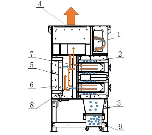
Fan Location and Static Pressure
In many cartridge dust collection systems, the fan is installed on the clean-air side, after the filter cartridges.
This induced-draft arrangement keeps much of the collector and inlet ductwork under negative pressure and avoids sending dirty process air directly through the fan.
Other arrangements are possible, but fan placement should be chosen from the complete system requirements.
For laser cutting, the most important issue is not simply whether the fan is mounted on top, beside, or behind the collector.
The critical question is:
Can the fan deliver the required airflow at the real system resistance?
That resistance includes:
table + active damper + duct + elbows + spark control + loaded cartridges + final filter + exhaust
Free-air fan capacity is not the operating airflow of the installed system.
Design for Loaded Filters, Not Only New Filters
A laser dust collector may perform very well immediately after installation.
The cartridges are clean, differential pressure is low, and table suction feels strong.
Then production begins.
Fine metal fume gradually loads the cartridges.
Resistance rises.
The fan operating point changes.
If the system has insufficient static-pressure reserve, airflow at the cutting table begins to fall.
Operators may then see smoke escaping from the table even though the fan motor is still running normally.
This is why the layout should be checked at the expected dirty-filter operating condition, not only with clean cartridges.
Differential-pressure monitoring provides an important indication of this change.
VFD control can also be useful where airflow demand changes with active table zones or filter loading.
The objective is not maximum fan speed.
It is stable source capture across the real operating cycle.
Exhaust Layout: Indoor Return or Outdoor Discharge
After filtration, clean air must go somewhere.
Some systems exhaust directly outdoors.
Others may return filtered air to the workshop where regulations, filtration performance, process dust, safety conditions, and local requirements allow it.
This decision affects the system layout because outlet ductwork also creates resistance.
Long exhaust ducts, silencers, afterfilters, weather hoods, and vertical stacks all add static pressure.
If the outlet path is designed after the fan has already been selected, the final system may not deliver the intended airflow.
The exhaust path belongs in the fan calculation from the beginning.
Dust Discharge Needs Its Own Maintenance Space
Fine dust released by pulse cleaning falls into the collector hopper and must be removed.
Possible arrangements include drawers, removable bins, drums, or other collection containers.
Whatever system is used, operators need enough space to remove it safely and regularly.
A large collector positioned against a wall may leave enough room for cartridge access but not enough room to pull out the dust bin.
That is still a poor layout.
Dust discharge also affects operating reliability.
If the hopper or bin is allowed to overfill, dust may re-enter the filter section, interfere with pulse cleaning, or create unnecessary maintenance and safety concerns.
Practical Layout Lessons from Industrial Applications
Case 1: Collector Installed Close to a Laser Table
A fabrication workshop had a laser cutting table in a crowded production area with limited space available for dust collection equipment.
Instead of using a distant collector with a long and complex duct run, a compact cartridge collector was installed near the cutting table.
The shorter duct reduced installation complexity and helped maintain effective fume capture while fitting within the available floor space.
Lesson: Collector location can reduce duct resistance and installation complexity when maintenance access is still preserved.
Case 2: Continuous Aluminum Cutting Overloaded the Existing System
Another fabrication operation performed aluminum laser cutting for long production periods.
The original extraction arrangement struggled with heavy fine fume loading and frequent cartridge problems.
The revised system focused not only on airflow, but also on greater filtration area, upstream hot-particle deflection, spark control, and automatic cartridge cleaning.
Lesson: Continuous production can turn a layout that works for occasional cutting into an undersized system.
Case 3: Frequent Filter Replacement in High-Production Laser Cutting
A high-production metal fabrication operation running around the clock was replacing collector filters approximately every month.
The redesigned system increased appropriate filtration capacity and reviewed the full extraction arrangement rather than simply replacing cartridges with another equivalent set.
Filter life increased substantially after the redesign.
Lesson: Repeated short cartridge life often points to a system-level problem involving filtration area, dust loading, airflow, or layout—not only the filter itself.
Central System or Dedicated Collector?
A dedicated collector for one laser machine generally makes airflow control simpler.
The duct path is easier to understand, and machine operation directly corresponds to collector demand.
Central systems can also work well, especially when several laser machines share one workshop.
But the layout becomes more complex.
Branch ducts, dampers, simultaneous machine operation, pressure balancing, fan control, and shutdown conditions all need to be considered.
If three machines connect to one collector but only one normally operates, the airflow control strategy should not behave the same way as when all three are cutting simultaneously.
Central systems therefore depend heavily on branch balancing and control logic.
Common Layout Mistakes
- Selecting the fan from maximum airflow but ignoring required static pressure.
- Pulling through the entire cutting table instead of controlling the active zone.
- Reusing existing duct diameter without checking the new airflow.
- Adding multiple elbows and transitions near the collector inlet.
- Installing spark control without including its pressure loss.
- Choosing a collector position that prevents cartridge or dust-bin access.
- Calculating airflow with clean filters only.
- Designing the exhaust duct after fan selection.
- Allowing long horizontal duct sections to accumulate dust.
- Connecting multiple machines without reviewing simultaneous airflow demand.
What Information Is Needed Before Designing the Layout?
Before finalizing the arrangement, collect:
- Laser power and cutting process
- Table dimensions and active extraction-zone design
- Metal types and thickness range
- Number of machines and simultaneous operating condition
- Required or existing airflow
- Duct diameter, length, elbows, and branches
- Available collector location and floor space
- Spark and hot-particle history
- Cartridge quantity, media area, and expected pressure drop
- Exhaust location and indoor/outdoor discharge plan
- Compressed-air supply for pulse cleaning
- Required cartridge, hopper, fan, and electrical maintenance access
A layout drawing with machine positions and approximate dimensions is often more useful than a collector model number alone.
Final Engineering View
A reliable laser cutting dust collection layout can be reduced to one airflow path:
Cutting Table → Active Zone → Ductwork → Spark Control → Filter Cartridges → Fan → Exhaust
and one dust path:
Filter Surface → Pulse Cleaning → Hopper → Dust Bin → Disposal
Every component affects the next.
Poor table zoning increases airflow demand.
Poor duct routing increases static pressure.
Poor spark control damages cartridges.
Too little filter area increases ΔP.
An undersized fan loses capture as filters load.
A poorly located collector makes routine maintenance difficult.
An overlooked exhaust duct changes the final fan operating point.
That is why the best system layout is not simply the one with the shortest duct or the largest fan.
It is the arrangement that maintains stable capture airflow at the active cutting zone while keeping duct resistance, spark exposure, filter loading, maintenance access, dust discharge, and total operating cost under control.
The most useful design question is therefore not:
“Where should we put the dust collector?”
It is:
“How should air and dust move through the entire system from the cutting source to final discharge?”
Once that path is clear, collector location, duct size, fan duty, filter area, spark control, and maintenance space can be selected as one coordinated system.
Frequently Asked Questions
Where should a laser cutting dust collector be installed?
It should generally be positioned to keep duct routing practical while maintaining adequate maintenance access, spark-control requirements, noise considerations, exhaust routing, and local safety clearances. A closer collector can reduce duct resistance, but proximity alone should not override service and safety requirements.
Should the fan be before or after the filter cartridges?
Many cartridge dust collectors use a clean-air-side induced-draft fan after the filters. Other arrangements are possible. The final configuration should match the dust, system pressure, fan type, and overall design.
Why is static pressure important in system layout?
Static pressure represents the resistance the fan must overcome from the cutting table, dampers, ductwork, elbows, spark-control devices, filter cartridges, dust cake, afterfilters, and exhaust path. If it is underestimated, actual airflow may be much lower than expected.
Should spark control be installed before the dust collector?
Hot-particle and spark control is generally positioned before the filter cartridges so that the filtration media is not the first component exposed to sparks or molten debris.
Is a short duct always better?
Shorter duct generally reduces resistance and installation complexity, but collector placement must also consider maintenance access, safety, noise, exhaust location, and workshop layout. The best arrangement balances all of these factors.
Can several laser cutting machines share one dust collector?
Yes, a central system can serve multiple machines when airflow, branch ducts, dampers, simultaneous machine operation, static pressure, filter area, and control logic are designed accordingly.
Author

Jessica Ma – Senior Filtration Engineer, Omela Filtration
Jessica Ma is a senior filtration engineer at Omela Filtration, specializing in dust and liquid filtration. With over 15 years of experience, she focuses on optimizing baghouse performance, enhancing filtration efficiency, and developing high-performance solutions for industrial dust collectors and precision liquid filtration applications.