Waste-to-Energy Dust Filtration
Waste-to-Energy Plants Dust Filtration Solutions
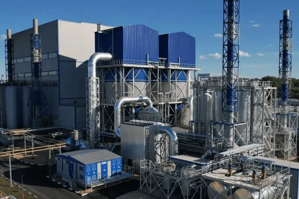
Waste-to-energy (WTE) plants face highly variable flue gas conditions due to inhomogeneous fuel quality. A well-designed baghouse system acts as the primary barrier for solid substances, delivering high collection efficiency for fine particulate while supporting stable pressure drop and efficient use of sorbents in modern flue gas treatment trains.
WTE projects often emphasize conservative and stability-oriented design, including:
- Low air-to-cloth ratio:
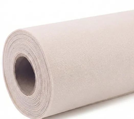
example value 2.3 ft/min (conservatively low vs similar facilities). - Advanced bag material:
PPS (“Ryton”) + PTFE laminate for improved filtration across particle sizes and easier cleaning. - On-line cleaning:
cleaning modules under normal operation to reduce downtime and improve stability. - Module dust monitors:
detect bag breaks early. - Side inlet gas introduction:
helps minimize unintended release of collected particulate.
WTE Process Stages & Filtration Challenges
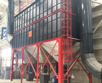
In WTE, the bag filter unit is the barrier for all solid substances within the flue gas treatment system, especially important under inhomogeneous fuel quality
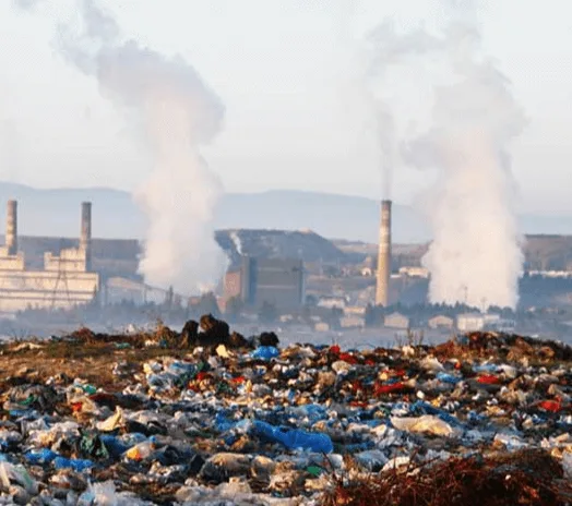
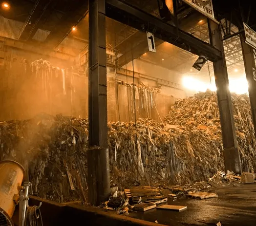
Waste Bunker & Feeding
- Variable waste composition
- Dust and odor containment requirements
- Continuous plant operation demands stability
Combustion & Boiler Flue Gas
- Fine particulate in combustion gases
- Fluctuating loading from fuel variability
- Tight compliance targets for PM control
Flue Gas Treatment (Dry / Semi-Dry Systems)
- Reactive dust + sorbents form filter cake
- Performance depends on stable filtration cycles
- Pressure drop stability becomes a key KPI
Ash Handling (Fly Ash / Residue)
- Fine, dispersible dust during discharge
- Controlled handling and testing requirements
- Minimizing unintended release is critical
Engineered Solutions
Omela Filtration Solutions for Waste-to-Energy Plants Dust
Waste-to-energy (WTE) plants operate under highly variable flue gas conditions due to heterogeneous waste composition and continuously changing combustion profiles. Fine particulate matter, reactive fly ash, and fluctuating dust loading place demanding requirements on dust filtration systems.
In modern WTE facilities, the baghouse is not only responsible for particulate removal, but also serves as a critical barrier for solid substances within the entire flue gas treatment system. Stable filtration performance is essential to support downstream emission control strategies and long-term regulatory compliance.
Unlike conventional industrial dust collection, WTE baghouses play an active role in flue gas treatment performance. The filter cake formed on the bag surface provides an additional filtration layer while allowing unreacted activated carbon and lime to remain in contact with the gas stream, improving overall pollutant control efficiency.

Typical Operating Conditions in Waste-to-Energy Plant Baghouses
| Process Section | Location | Normal Gas Temp. | Peak Temp. | Dust Characteristics | Operating Mode |
| Waste Feeding & Combustion | Furnace outlet / boiler inlet | 160–200 °C | 220–240 °C | Fine particulate, reactive fly ash, variable composition | Continuous, variable fuel quality |
| Boiler Flue Gas | Boiler outlet / duct to baghouse | 150–180 °C | 200–220 °C | Fine fly ash, acidic components, sorbent-laden dust | Continuous, variable load conditions |
| Dry / Semi-Dry Scrubber Outlet | CDS or spray dryer outlet | 130–170 °C | 190 °C | Reactive dust with lime and activated carbon | Continuous, reaction-dependent filtration |
| Baghouse Filtration Zone | Filter compartment | 130–160 °C | 180 °C | Very fine particulate, chemically active filter cake | Continuous, on-line pulse cleaning |
| Residue & Fly Ash Discharge | Baghouse hopper / ash handling | 100–140 °C | 160 °C | Fine, dispersible ash with sorbent residue | Continuous with controlled discharge |
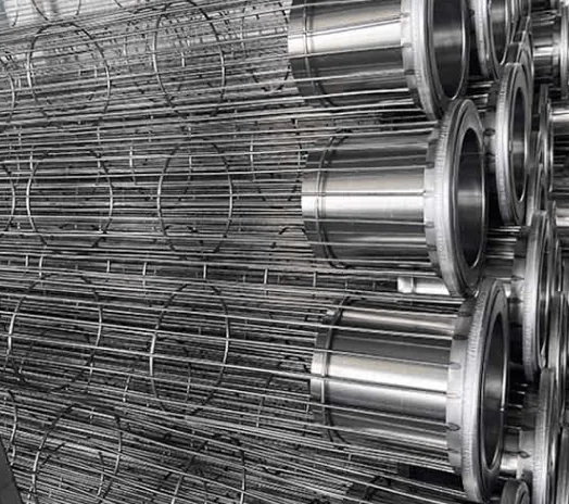
Recommended Filter Bag Constructions for Waste-to-Energy Applications
| Process Section | Recommended Media | Felt Weight | Finish / Surface Treatment | Typical Bag Design | Cage Recommendation |
| Waste Feeding & Combustion | PPS needle felt | 500–550 g/m² | Calendered, singed | Pulse-jet bags with reinforced top cuff | Carbon steel cage, standard wire spacing |
| Boiler Flue Gas | PPS needle felt with PTFE membrane | 500–600 g/m² | PTFE membrane, acid & alkali resistant finish | High-temperature pulse-jet bags | Carbon or stainless steel cage, reinforced design |
| Dry / Semi-Dry Scrubber Outlet | PPS or P84 / PPS blend | 500–600 g/m² | PTFE surface treatment to reduce blinding | Reinforced seams, wear patches at contact points | Stainless steel cage, reinforced bottom ring |
| Baghouse Filtration Zone | P84 polyimide filter media | 500–550 g/m² | PTFE membrane or surface finish for stable DP | Precision pulse-jet bags for long filtration cycles | Stainless steel cage, close pitch spacing |
| Residue & Fly Ash Discharge | PPS or fiberglass with PTFE membrane | 550–800 g/m² (fiberglass) | Anti-adhesion, chemical-resistant finish | Heavy-duty bags with reinforced bottom | Stainless steel cage, 12–16 vertical wires |
450 t/d Waste-to-Energy Plant – Baghouse Emissions Stabilization South Africa
The existing baghouse at a waste-to-energy (WTE) plant was suffering from unstable differential pressure, elevated stack particulate emissions, and frequent cleaning upsets due to variable waste composition and highly reactive dust (lime/activated carbon residue).The plant needed a cost-effective upgrade to achieve stable low emissions, improve long-term reliability, and optimize sorbent performance in the flue gas treatment train.
Operating Conditions & Challenges
| Gas Temperature | 130–170 °C (peak 190 °C) |
| Dust Loading | 25–45 g/Nm³, fine reactive fly ash with sorbent residue |
| Dust Characteristics | Very fine particulate, chemically active filter cake (lime & activated carbon), adhesion tendency |
| Air-to-Cloth Ratio | 0.9–1.2 m/min |
| Existing Emissions | ≈ 35–55 mg/Nm³ |
| Existing DP | 1,700–2,400 Pa, unstable |
Omela Engineering Solution
- Filter Media & Bag Design (P84® polyimide or PPS + PTFE membrane for fine reactive dust)
- Cage & Hardware Upgrade (reinforced cages, improved bag-to-tube-sheet sealing)
- Pulse Jet Cleaning Optimization (stable filter cake control, reduced DP fluctuation)
- Leak Detection & Sealing (module sealing and leak-point rectification)
After the upgrade with Omela’s high-performance filter bags and baghouse tuning, particulate emissions have remained consistently below 20 mg/Nm³.
Differential pressure is now stable, and cleaning performance has become much more reliable under variable waste conditions.
50%

Annual Cost Reduction
Lower bag replacement frequency, fewer baghouse upsets, and reduced compressed air usage cut overall WTE baghouse operating cost by up to 50%.
Measured Results
| Parameter | Before Upgrade | After Omela Solution |
| Stack Emissions | 35–55 mg/Nm³ | 10–18 mg/Nm³ |
| Differential Pressure | 1,700–2,400 Pa (unstable) | 1,100–1,400 Pa (stable) |
| Filter Bag Service Life | 9–12 months (average) | Target 24–30 months (projected, based on first 12 months) |
| Unplanned Shutdowns | 3–5 per year | 1 per year (for inspection only) |
| Compressed Air Consumption | 100% | ≈ 10–18% reduction |
Reduce
Filtration Costs
Significantly
Longer bag life, fewer change-outs, and lower total cost of ownership (TCO). Let our experts show you how much you can save.
Frequest Asked Questions
In waste-to-energy (WTE) plants, the baghouse functions as the primary barrier for all solid substances in the flue gas stream.
According to operational design principles used in modern WTE facilities:
- The baghouse removes
over 99.5% of particulate matter
from combustion gases - It works downstream of
circulating dry scrubbers (CDS)
or similar dry/semi-dry systems - Each boiler typically has its
own dedicated baghouse system
to ensure stable operation
Filter cake plays a critical functional role in WTE applications, beyond basic dust collection:
The filter cake serves two key purposes:
- Improved particulate removal
The accumulated cake acts as an additional filtration layer,
enhancing fine particle capture. - Extended reaction time for reagents
Unreacted activated carbon and lime trapped in the cake remain
in contact with the flue gas longer, improving control of:- Acid gases
- Mercury
- Dioxins and furans
This dual function is a defining characteristic of WTE baghouse operation.
WTE baghouses use pulse-jet cleaning systems:
- Strong bursts of compressed air periodically remove collected dust and reacted
sorbents from the bag surface - Cleaning occurs on-line, meaning:
- The baghouse remains in operation
- Combustion stability is maintained
- Downtime is minimized
Some of the removed material may be recirculated back to the CDS reactor, while the remainder is combined with bottom ash.
In modern WTE facilities:
- Collected fly ash, spent lime, and activated carbon are:
- Either recirculated
- Or combined with bottom ash
- The combined ash is routinely tested to confirm it is
non-hazardous under regulatory standards
This handling strategy is an integral part of WTE flue gas treatment system design.
WTE baghouses are designed with a conservatively low air-to-cloth (A/C) ratio to ensure stable performance.
A typical design value highlighted in reference projects is:
- ~2.3 ft/min, which is lower than many comparable industrial baghouses
Benefits include:
- Improved filtration stability
- Better filter cake control
- Reduced pressure drop fluctuation
- Greater operational margin under variable waste composition
A widely adopted configuration in WTE plants is:
- PPS (Ryton®) filter bags with PTFE laminate
- PPS offers improved robustness compared to fiberglass
- PTFE laminate enhances filtration efficiency across all particle sizes
- The membrane also facilitates easier cleaning and more stable pressure drop
For higher-temperature or more demanding conditions,high-temperature filter media such as P84® polyimide may also be considered.
Modern WTE baghouses often incorporate:
- Dust monitors on each module
These monitors:
- Help detect bag breaks at an early stage
- Reduce the risk of uncontrolled emissions
- Support preventive maintenance strategies
Side-inlet introduction of flue gas into baghouse modules is used to:
- Minimize the unintended release of collected particulate
- Improve dust distribution across filter bags
- Enhance overall filtration stability
This design feature is commonly specified in state-of-the-art WTE baghouse systems.
Key differences include:
- Highly variable fuel composition
- Reactive dust containing sorbents
- Filtration that directly supports chemical pollutant control
- Greater emphasis on:
- Filter cake management
- Pressure stability
- Long filtration cycles
As a result, WTE filtration systems are designed as part of an integrated flue gas treatment process, not as standalone dust collectors.
To evaluate or optimize a WTE baghouse system, the following information is typically required:
- Flue gas temperature range
- Type of scrubbing system (CDS / dry / semi-dry)
- Dust loading and sorbent usage
- Target emission limits
- Existing air-to-cloth ratio and cleaning mode
Accurate process data allows for proper media selection and long-term
stable operation.