
Key Takeaways
- Filtration velocity and can velocity describe different restrictions. The air-to-media ratio indicates average flow through filter media; the open flow passages in a cartridge dust collector determine how rapidly dusty air moves around the elements.
- Upward airflow can undo a successful cleaning pulse. Released particles may be carried back onto cartridge surfaces instead of settling into the hopper, even when the nominal air-to-media ratio looks acceptable.
- Calculate geometry at the location being studied. Omela’s baghouse design calculators illustrate can and interstitial velocity for bag arrangements, but cartridge layouts require their own projected-area and flow-path checks.
- Downflow can assist dust discharge, but it is not automatically superior in every application. Compare the inlet configuration, dust characteristics, and pulse-cleaning performance rather than selecting equipment by cartridge orientation alone.
- Use operating evidence to validate the design. Compare hopper discharge, airflow, and pressure trends with the cartridge collector maintenance guidance and the separate advice on cartridge cleaning versus replacement.
Why Two Collectors with the Same Filter Area Can Behave Differently
A plant engineer may see two proposals with identical rated airflow, filter quantity, and nominal filtration area. One collector operates at a stable differential pressure and discharges dust into its hopper. The other pulses frequently, loses suction, and accumulates a stubborn dust layer. What explains the difference?
One possibility is the path taken by incoming dusty air. Air moving through the media and air moving around cartridges are not the same velocity. The space between filter elements, the inlet location, the housing cross-section, and the direction of flow determine whether detached dust can move away from the filters after cleaning.
This distinction is especially important for lightweight welding fume, laser-cutting particulate, fine mineral dust, and other materials that settle slowly. A reasonably low air-to-media ratio does not guarantee reliable online pulse cleaning if the surrounding airflow continually carries released dust back into the cartridge bank.
The following calculations are preliminary screening methods. They cannot substitute for application-specific dust testing, manufacturer drawings, or measurements of a complicated internal flow field.
Three Velocities Engineers Should Keep Separate
Filtration Velocity: Flow Through the Media
Filtration velocity is total actual airflow divided by the qualifying filter-media area:
Vf = Q / Am
Here, Q is actual volumetric flow at collector conditions, and Am is the media area used in the rating. With Q in m³/min and area in m², the result is m/min. Using CFM and square feet gives ft/min, commonly expressed as an air-to-media ratio.
It is an average over the media, not a direct measurement at each pleat. Pleat spacing, permeability, dust cake, and cartridge construction can make the useful flow distribution nonuniform. For this reason, increasing the advertised media area does not automatically correct poor cleaning or excessive pressure drop.
Can Velocity: Flow in the Housing
Terminology varies by source. In traditional bottom-entry baghouse design, can velocity often means the upward speed in the open lower chamber, calculated as Q / Ah, where Ah is the housing cross-sectional area. Interstitial velocity is calculated above the filter bottoms where bags occupy part of the flow passage.
ASHRAE describes dusty-air approach or can velocity more generally using the net open cross-section around the filters. In a simple vertical upflow geometry, that is:
Vopen = Q / (Ah − ΣAf)
ΣAf is the area physically blocked by filters at the plane perpendicular to the upward flow. The resulting net-area value may also be called interstitial velocity. Always state where the cross-section is taken and which area was subtracted; otherwise two apparently different “can velocity” calculations may simply use different definitions.
Filter-Periphery Velocity: Flow Near the Pleats
Cartridge collectors add another consideration. A pleated cylindrical cartridge has a large unfolded media area but a much smaller outer envelope. An approximate filter-periphery face velocity for identical cylindrical cartridges is:
Vp = Q / (N × π × D × L)
Here N is cartridge count, D is outside diameter, and L is exposed length. This uses the external cylindrical envelope, not the unfolded pleated area. It is a screening measure of how strongly air approaches the cartridge surface; actual local velocity varies with arrangement and inlet distribution. It should never be mistaken for filtration velocity or assigned a universal acceptable limit.
| Velocity | Basic area in denominator | Best used to assess |
|---|---|---|
| Filtration velocity (Vf) | Rated or effective media area | Average media loading, pressure drop, filtration duty |
| Lower-chamber can velocity | Unobstructed housing cross-section below filters | Bulk upward flow entering the filter zone |
| Interstitial or net-area approach velocity | Housing section less obstructing filter projections | Upward flow through gaps between filters |
| Cartridge periphery velocity | Outer cartridge envelope area | Local approach and possible immediate re-deposition |
Worked CFM Example: Same Media Area, Different Air Path
Consider a hypothetical vertical upflow cartridge collector with a design flow of 7,200 m³/h, equivalent to 120 m³/min. It has 12 vertically installed cylindrical cartridges, each assumed to provide 15 m² of rated media area, with an outside diameter of 0.32 m and exposed length of 1.2 m. The dusty-air housing at the relevant plane measures 2.5 m × 2.0 m.
First, filtration velocity is 120 / (12 × 15) = 0.667 m/min. That is the average media face velocity, about 2.19 ft/min. It says little by itself about the speed of dusty air rising around the cartridges.
Second, the gross housing area is 5.00 m². Gross lower-chamber velocity is 120 / 5.00 = 24.0 m/min, or approximately 79 ft/min.
Third, if all 12 cartridges cross the analyzed horizontal plane, their combined projected area is 12 × π × (0.32 / 2)² = 0.965 m². The open area becomes 4.035 m². Upward net-area velocity is approximately 29.7 m/min, or 98 ft/min.
Finally, outer-envelope area is 12 × π × 0.32 × 1.2 = 14.48 m², giving an illustrative cartridge-periphery velocity of 8.29 m/min, or 27.2 ft/min.
| Example calculation | Result | What the result does not establish |
|---|---|---|
| Average filtration velocity | 0.667 m/min | That dust will release effectively |
| Gross lower-chamber can velocity | 24.0 m/min | Maximum velocity beside each cartridge |
| Net-area upward velocity | 29.7 m/min | Local velocity throughout the entire collector |
| Outer-periphery velocity | 8.29 m/min | A universally acceptable cartridge design limit |
These quantities are not interchangeable. The example assumes uniform upward flow and identical cartridges crossing one plane. Multi-level arrays, oval filters, sideways cartridges, inlet baffles, and nonuniform flow require geometry-specific calculations and often detailed flow analysis.
How High Upward Velocity Causes Dust Re-Entrainment
Pulse cleaning briefly reverses flow through the media and releases part of the dust cake. The released dust should then separate from the cartridge surfaces and move into the hopper. In a strong upward airstream, fine particles may slow, remain suspended, or return to neighboring filters after the cleaning pulse ends.
The result can be a frustrating operating pattern: cleaning appears to work momentarily, then the differential pressure rebounds. The controller pulses again, consuming compressed air while relatively little dust reaches the discharge container. Eventually, a persistent residual cake forms in pleat valleys or on cartridge surfaces.
The problem is not described by one universal settling-velocity threshold. Real industrial dust contains particles of different sizes and densities; agglomeration, turbulence, moisture, electrostatic effects, and local jets all influence deposition. Inlet dust loading also matters: an otherwise acceptable velocity may become problematic when production increases dramatically.
High upward velocity should therefore be treated as a design risk to investigate, not as a certain diagnosis every time pressure drop increases. Incorrect DP instrumentation, insufficient compressed-air pressure, failed valves, plugged hoppers, wet dust, and unsuitable media can produce similar symptoms.
Downflow Design: Why Direction Can Matter More Than Cartridge Orientation
In a conventional bottom-entry upflow unit, detached dust often has to fall against incoming dirty air. A downflow design introduces air so that much of the dusty stream moves downward near the filters, helping heavier particles reach the hopper and reducing immediate re-entrainment.
This does not mean all downflow designs are identical or every horizontal-cartridge unit will perform better than a vertical-cartridge unit. A poorly positioned inlet, an abrupt transition, or uneven distribution can still strike the media with high local velocity. Similarly, a well-designed side-inlet or vertical-cartridge collector can work effectively when the dust, velocities, and cleaning arrangement are properly matched.
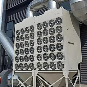
For a new system, review inlet elevation, baffles or diffusion arrangements, clearance around filter banks, hopper entry, and dust-removal equipment. For a retrofit, compare changing airflow direction, adding a suitable inlet section, reducing localized jets, or increasing useful flow passage area with the costs of a complete collector replacement.
Cartridge pleat depth and spacing also matter. Even after the bulk flow is improved, fine dust trapped between closely spaced pleats may be difficult to discharge. Neither downflow nor a low nominal air-to-media ratio eliminates the need for appropriate filter media and pulse-energy distribution.
What Published Industrial Cases and Experiments Teach Us
The following are independent third-party reports or published research, not Omela installations. They provide specific observations but cannot define safe velocity limits for all cartridge collectors.
Glass Manufacturing: Low Nominal Velocities Hid a Local Flow Problem
A published engineering investigation described a glass-making plant filtering very fine, lightweight silica dust. The cartridge collector initially operated below 5 in. w.g. pressure drop but soon reached approximately 11 in. w.g.; reported airflow was only 36% of design. Cleaning and replacing cartridges did not produce a lasting solution.
The consultant reported a 2.5:1 air-to-media ratio, 53 ft/min lower-chamber can velocity, and 112 ft/min interstitial velocity. However, the calculated cartridge-periphery velocity was approximately 68 ft/min. After manual filter cleaning, DP briefly fell to 3 in. w.g. and returned to 11 in. w.g. within three days, with little dust reaching the receiving bin.
Based on his experience with that particular silica dust, the consultant considered roughly 25 ft/min periphery velocity more workable and recommended redesign with greater effective capacity. That was a site-specific engineering judgment, not an industry-wide limit. The source documents the recommendation, not a measured post-retrofit outcome.
Plasma Cutting: Short Filter Life Had Several Causes
In a field report involving three plasma-cutting stations, cartridge service life fell from more than one year to about three months. The installed collector had a reported 3,000 CFM design flow and 2.3:1 air-to-media ratio. Investigation found dust accumulation within pleats, cleaning pressure set above the equipment recommendation, and duct velocities substantially above the original design.
The most important discovery was a change in production: the process had shifted from roughly 600 manually cut pieces to more than 1,500 robotic-cut pieces. The dust load had grown far beyond the original operating assumptions. This case shows that shorter cartridge life cannot automatically be blamed on can velocity. Airflow, loading, pulse settings, material condition, and production changes must all be checked.
Pilot-Scale Research: Released Dust Can Re-Deposit After Pulsing
A peer-reviewed 2023 experiment studied dust re-deposition in a pilot-scale cartridge collector using a vertically installed pleated element. Under the tested conditions, researchers compared one continuous pulse with a sequence of separated pulses having the same total pulse duration. Reported re-deposition fell from 63.8% in the single-pulse case to 24.4% with the five-pulse arrangement.
This experiment did not establish a can-velocity threshold or prove that multi-pulsing is optimal for industrial installations. It does support an important mechanism: the time available for dislodged particles to leave the filter zone influences cleaning effectiveness. Bulk flow direction and cleaning-pulse design need to be evaluated together.
Practical Design and Troubleshooting Checklist
- Confirm airflow: Measure actual volume at operating temperature and pressure rather than relying only on fan nameplate CFM.
- Document geometry: Record housing internal dimensions, cartridge diameter, length, arrangement, and how much space is blocked at each relevant cross-section.
- Calculate the distinct velocities: Check media filtration velocity, lower-chamber speed, net-area velocity, and cartridge-envelope velocity where the design permits meaningful estimates.
- Inspect the inlet and hopper: Identify localized jets, upward paths, poor baffles, dust bridging, and whether released material actually reaches the discharge.
- Trend cleaning performance: Record DP before and after pulses, fan speed, compressed-air quality, and hopper discharge at comparable production loading.
- Investigate process changes: Check dust concentration, particle size, moisture, production throughput, and any duct or fan modifications since commissioning.
- Verify safety before retrofitting: Assess combustible-dust hazards, ignition sources, explosion protection, and safe access. Do not alter ducts or collector internals without appropriate engineering review.
Final Engineering Recommendation
Do not size a cartridge collector by media area alone. Begin with the required airflow and dust properties, then examine the housing passages, inlet direction, cartridge envelope, and pulse-cleaning response. A low filtration velocity can coexist with strong local air movement that returns dislodged dust to the filters.
The best design decision is supported by geometry, realistic dust-loading assumptions, measured pressure trends, and evidence that discharged dust reaches the hopper. If repeated filter changes do not solve high DP, investigate the flow path before purchasing more cartridges or increasing pulse pressure.
FAQ
What Is the Difference Between Can Velocity and Filtration Velocity in a Cartridge Dust Collector?
Filtration velocity divides airflow by filter-media area. Can velocity describes dusty-air movement within the collector housing; depending on the definition and location, it may use the gross lower-chamber area or the net open area around filters. They measure different aspects of collector performance.
How Do You Calculate Can Velocity from CFM?
For a simple bottom-entry chamber, divide actual CFM by the unobstructed chamber area in square feet. For flow between cartridges, subtract the area blocked by the cartridges at the analyzed cross-section before dividing. Complex layouts need separate flow-path analysis.
Why Can Low Air-to-Media Ratio Still Lead to Poor Pulse Cleaning?
The nominal media area can be large while open passages or local cartridge-envelope area remain relatively small. Released dust may be carried back onto the filters by upward or disturbed airflow. Verify dust loading, pressure trends, and the actual internal flow arrangement.
Is Downflow Always Better Than Upflow for Cartridge Dust Collectors?
No. Downward airflow can assist dust movement toward the hopper and reduce re-entrainment, particularly for light dust, but the result also depends on inlet distribution, filter spacing, dust properties, cleaning system, and overall collector design.
Is There a Universal Safe Can Velocity or Interstitial Velocity for Cartridge Filters?
No. Appropriate limits depend on dust density, particle distribution, concentration, humidity, inlet geometry, and filter configuration. Published values for baghouses or specific factory cases should not be treated as universal cartridge-collector design limits.
Author

Jessica Ma – Senior Filtration Engineer, Omela Filtration
Jessica Ma is a senior filtration engineer at Omela Filtration, specializing in dust and liquid filtration. With over 15 years of experience, she focuses on optimizing baghouse performance, enhancing filtration efficiency, and developing high-performance solutions for industrial dust collectors and precision liquid filtration applications.