
Key Takeaways
- Start with the process duty, not the cartridge length. Establish peak liquid flow, viscosity, temperature, solids loading, and required retention before choosing industrial liquid filter cartridges.
- Use a model-specific flow-versus-pressure-drop curve. A cartridge’s nominal length or advertised media area does not establish the allowable flow at your required initial differential pressure.
- Cartridge quantity is a hydraulic calculation. Divide design flow by a qualified flow per element, round up, and then check the complete vessel and the operating margin.
- Effective area influences flux, but does not independently predict life. Compare pleated membrane filter cartridges and depth media by measured performance, removal rating, and solids behavior.
- Separate sizing from physical compatibility. For cartridge lengths, end connections, and vessel geometry, use the cartridge length and housing size guide; for abnormal loading, consult the premature cartridge plugging guide.
Why Filter Cartridge Sizing Is More Than Dividing Flow by Length
A 30 m³/h plant might receive proposals for eight or twelve cartridges at the same micron rating. Which is correctly sized? The answer depends on the exact media curve, flow distribution, and contaminant loading—not cartridge count alone.
Undersizing increases initial resistance and can shorten service intervals; excessive oversizing increases capital cost. A poorly matched housing may also cause bypass.
The defensible sequence is fluid and retention specification → qualified element flow → cartridge count → clean and loaded pressure budget → trial-based life estimate → vessel verification. This article develops that calculation rather than repeating a product-length comparison.
Step 1: Define the Liquid, Solids, and Retention Requirement
What to Record Before Using a Flow Curve
Clean-water flow charts may not suit viscous chemicals or gel-containing liquids. Record peak flow, batch duration, operating viscosity and temperature, chemistry, and solids properties.
Retention must also be defined correctly. A nominal 5 µm depth filter and an absolute-rated 5 µm membrane are not interchangeable performance claims. Specify the required removal efficiency or test standard when downstream equipment or product quality depends on it. Check compatibility of the media, support core, end caps, seals, and any cleaning chemicals.
For solids loading, an inlet concentration is helpful but incomplete. Hard mineral particles, soft gels, deformable biological material, and emulsified droplets can create very different pressure-rise profiles at the same mass concentration. Where the process fluctuates, obtain representative samples from both typical and worst-case conditions.
Why Media Construction Changes the Calculation
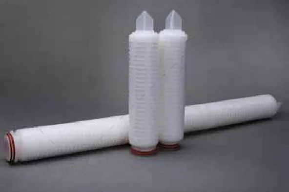
Pleated filters provide substantial media surface; depth cartridges retain solids through their thickness. Neither guarantees a particular dirt capacity, and crowded pleats can limit accessible area.
Choose the retention mechanism first. Then use the manufacturer’s performance data for that specific grade—not a generic flow allowance per inch—to size the bank. Nominal area alone may hide differences in resistance and loading.
Step 2: Calculate Flow per Cartridge and Required Quantity
Use the Recommended Flow, Not Just the Maximum
Factory Direct Filtration describes an initial length-based approach using a 10-inch cartridge’s flow rating and scaling it for longer elements. That is useful for rough screening only where the manufacturer confirms proportionality for the same series. A 40-inch cartridge is not automatically four times the practical capacity of a 10-inch cartridge at every retention grade or fluid viscosity.
Pall’s published selection methodology separates recommended liquid flow from maximum flow and points users to the relevant filter data sheet for pressure loss. This distinction matters because a filter operating near its maximum hydraulic rating may have little allowance for solids accumulation or process variation.
For parallel identical cartridges, the preliminary relationship is:
Minimum cartridge count, N = round up (Qdesign ÷ qqualified)
Here, Qdesign is the maximum flow the operating bank must handle, and qqualified is the per-cartridge flow supported by the applicable clean pressure-drop curve and application conditions. If a duty requires uninterrupted flow during maintenance, size the remaining operating train for that condition rather than counting an isolated standby vessel as available capacity.
Worked Example: A 30 m³/h Process-Water Filter
Assume a hypothetical plant filters water at 25°C with a maximum design flow of 30 m³/h and a 5 µm particulate target. A supplier’s application-specific curve is assumed to qualify a particular 40-inch pleated cartridge at 3.0 m³/h, with a clean cartridge differential pressure of 0.10 bar at that point.
The arithmetic minimum is 30 ÷ 3.0 = 10 cartridges. A designer might investigate a 12-cartridge housing to lower per-element loading to 2.5 m³/h and allow operating margin. The clean pressure drop at 2.5 m³/h must be read from the manufacturer’s curve; it should not be invented by multiplying the 0.10-bar value by a convenient factor.
| Item | Illustrative value | Sizing interpretation |
|---|---|---|
| Maximum operating flow | 30 m³/h | Must be handled at the design condition |
| Qualified flow per selected 40-inch element | 3.0 m³/h | Hypothetical vendor-curve value, not an Omela rating |
| Arithmetic minimum | 10 elements | 30 ÷ 3.0, rounded up |
| Preliminary bank for evaluation | 12 elements | 2.5 m³/h per element at peak flow |
| Assumed usable media area | 2.0 m² per element | Only if confirmed for this exact cartridge |
| Total assumed area at 12 elements | 24 m² | Illustrative average flux = 1.25 m³/(m²·h) |
These numbers are a teaching example, not verified performance for an Omela SKU or a universal 40-inch cartridge rule. An actual quotation should attach the relevant media grade, curve, temperature basis, and mechanical limits.
Step 3: Use Effective Filter Area Without Overinterpreting It
A useful average flux expression is J = Q ÷ Aeffective, where Q is volumetric flow and Aeffective is the wetted media area supported by the manufacturer’s definition. In the example, 30 m³/h divided by 24 m² gives 1.25 m³/(m²·h), or about 20.8 L/(m²·min).
Flux helps compare loading intensity for related media designs. It does not determine removal efficiency or service life by itself. Media permeability, pleat spacing, pore structure, surface chemistry, and the distribution of flow through the vessel all affect performance. Even the advertised pleated area may not equal the area carrying uniform flow in service.
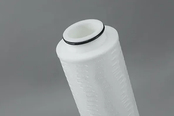
For two alternative cartridge models, first compare their pressure-drop curves at the same fluid viscosity, retention target, and total flow. Then examine the accessible area and the results of representative loading trials. A larger area may lower local flux, but it is not a substitute for matching the contaminant to the media.
Step 4: Check Clean and Loaded Pressure Drop
Three Limits That Must Not Be Confused
Clean differential pressure is the resistance of a new filter at the specified flow and fluid conditions. Changeout differential pressure is the operating threshold at which the plant replaces or services elements. Maximum allowable differential pressure is a mechanical limit for the cartridge or assembly, often dependent on temperature and flow direction. The housing also has a separate maximum allowable operating pressure.
The pressure budget includes media, vessel, connections, and piping at the same flow. Check the pump curve at both clean and expected terminal resistance.
| Sizing check | Engineering question | Evidence needed |
|---|---|---|
| Clean cartridge ΔP | Is initial resistance acceptable at design flow? | Exact grade’s flow–ΔP curve |
| Housing and connection losses | Do nozzles, supports, or piping restrict flow? | Vessel data and hydraulic calculation |
| Loaded/changeout ΔP | Can the pump maintain required flow before replacement? | Trend or representative fouling trial |
| Mechanical ΔP limit | Could the element deform or collapse? | Element rating at temperature and flow direction |
| Vessel operating pressure | Is the housing suitable for the line pressure? | Nameplate, drawings, and applicable code |
Why Viscosity and Temperature Change the Result
As temperature falls, viscosity can increase, making clean-water sizing inappropriate for oil, syrup, or polymer solutions. Use a supplier-approved correction within its stated applicability.
Temperature also affects material strength, gasket compatibility, and the element’s permitted differential pressure. Check those limits independently of the initial hydraulic calculation. A pressure rating quoted at ambient temperature may not apply at process temperature.
Step 5: Estimate Service Life from Loading, Not Calendar Assumptions
Service life is the period during which the cartridge continues to meet the required quality and hydraulic limits. It cannot be predicted reliably from clean-water flow or media area alone. A change in particle-size distribution, gel content, biological growth, or upstream pretreatment may shorten life even when total flow stays constant.
A preliminary contaminant mass balance can reveal the scale of the duty. For example, 30 m³/h at 8 mg/L suspended solids introduces 0.24 kg of solids per hour. If an assumed 75% is retained, the cartridge bank captures about 0.18 kg/h. This is a hypothetical loading calculation—not proof of the bank’s dirt capacity or its likely replacement date. Actual retained mass and pressure rise require a suitable trial or validated model.
During commissioning, measure clean ΔP, treated volume, flow, temperature, inlet quality, and outlet quality. Trend ΔP at comparable flow until the approved changeout criterion approaches. If retention performance or mechanical integrity fails earlier, replace before reaching the pressure threshold. Evaluate at least one realistic production cycle rather than relying on a theoretical dirt-capacity number.
What Published Industrial Cases Teach Us
These examples come from independent research and third-party supplier reports, not Omela installations. They support the engineering principles but do not establish performance guarantees for other cartridges.
Louisiana Chemical Plant: Poor Flow Geometry Shortened Element Life
A chemical plant’s deep-well injection filtration system experienced frequent failures. In Waco’s published account, cartridges contacted one another inside the vessel, limiting effective flow paths; increasing differential pressure also contributed to element separation and bypass. The previous filters lasted approximately 24 hours and required daily service.
After an application-specific cartridge and changeout arrangement was introduced, Waco reported filter life increasing to 36 hours and maintenance duration falling from 45 to 10 minutes. The supplier also estimated 30 additional operating hours per week. The lesson is that nominal cartridge count is meaningless if the elements cannot operate with the intended flow distribution and mechanical support.
Mississippi Refinery: Viscosity and Collapse Resistance
Total Filtration Services reported that a refinery filtering high-viscosity recovered petroleum liquids experienced cartridge warping and collapse within about a week. An initial high-flow trial identified the need for stronger media and support structures. A subsequent trial used 12 modified cartridges, and the supplier reported acceptable filtration without the earlier deformation.
The public account does not give an independently verified new changeout interval. Its value is in demonstrating why viscosity, differential-pressure loading, core strength, and flow direction must be checked together. A cartridge bank may have adequate nominal area while the elements lack the mechanical capacity for the duty.
Full-Scale Desalination: The Economic Value of Comparing Cartridges
In a peer-reviewed study at the Dhekelia desalination plant in Cyprus, researchers compared seven commercial high-flow cartridge types ahead of reverse osmosis. They evaluated produced-water quantity, quality, and filtration operating cost. The best option delivered 34% more water with improved measured water quality than the comparison baseline, while replacing the worst-performing option with the best was estimated to reduce cartridge-filtration operating cost by about 39% under the study conditions.
The researchers also examined how electricity price affects the economic replacement point as differential pressure increases. This is stronger evidence than a catalog flow rating for the importance of measuring both hydraulic resistance and useful throughput. It does not mean every new cartridge will deliver similar savings.
Practical Sizing and Verification Checklist
- Define the duty: Maximum flow, batch or continuous operation, temperature, viscosity, chemistry, solids load, retention efficiency, and downstream quality requirement.
- Qualify the element: Confirm media compatibility, end connection, flow direction, model-specific flow–ΔP curve, and mechanical limits.
- Calculate the bank: Round up design flow divided by qualified per-element flow; then evaluate margin, uneven flow distribution, and standby requirements.
- Check pressure at both ends of life: Include cartridge, housing, connections, piping, and available pump head at clean and loaded conditions.
- Validate with evidence: Collect representative fouling data, pressure trends, filtrate quality, changeout labor, disposal cost, and any integrity-test requirements.
Final Engineering Recommendation
Industrial liquid cartridge sizing should end with a documented, testable operating envelope: how much liquid must pass, at what removal performance, through how many compatible elements, with how much pressure loss, for how long. Quantity alone is not the final decision.
Choose the exact media grade first, calculate quantity from qualified flow and pressure-drop data, and test how the selected configuration responds to real contamination. Compare treated volume, quality, energy, changeout cost, and downtime—not price alone.
FAQ
How Do You Calculate the Number of Industrial Liquid Filter Cartridges?
Divide maximum design flow by the qualified flow per cartridge at the specified micron rating, fluid conditions, and clean pressure-drop target, then round up. Review housing flow distribution, fouling margin, and redundancy before finalizing the count.
Can Effective Filter Area Alone Determine Cartridge Flow Rate?
No. Effective area helps calculate average filtration flux, but flow also depends on media permeability, retention grade, pleat geometry, viscosity, and allowable pressure drop. Use the specific cartridge’s validated flow–pressure-drop data.
What Is the Difference Between Clean Pressure Drop and Changeout Pressure Drop?
Clean pressure drop is the resistance of a new element at a stated flow. Changeout pressure drop is the operating threshold for replacement. Neither should be confused with the cartridge’s mechanical maximum differential-pressure rating.
How Does Liquid Viscosity Affect Cartridge Quantity?
More viscous liquid generally increases resistance at a given flow, although the exact response depends on the media and flow regime. Use performance data or an approved viscosity correction at operating temperature; additional cartridges may be required.
How Can You Estimate Filter Cartridge Service Life Before Purchase?
Use representative liquid samples and a trial or validated loading test to track pressure rise, treated volume, and outlet quality. Clean-water ratings, cartridge length, or a generic calendar interval cannot reliably predict useful life by themselves.
Author

Jessica Ma – Senior Filtration Engineer, Omela Filtration
Jessica Ma is a senior filtration engineer at Omela Filtration, specializing in dust and liquid filtration. With over 15 years of experience, she focuses on optimizing baghouse performance, enhancing filtration efficiency, and developing high-performance solutions for industrial dust collectors and precision liquid filtration applications.