
Key Takeaways
- A tube sheet is a sealing interface, not merely a perforated steel plate. In a pulse-jet baghouse, each opening must accommodate the specified bag-top attachment while separating the dusty and clean-air chambers.
- Hole diameter, roundness, edge finish, and plate thickness work together. Even well-made dust filter bags may bypass dust when a snap band cannot seat consistently.
- Welding can change an initially accurate plate. Fabrication checks should follow major joining and straightening operations rather than relying only on a pre-weld cutting report.
- The bag, tube sheet, and filter bag cages form one assembly. Verify the actual interface with sample components, especially on repairs and retrofits.
- Leak testing validates a completed installation; it does not replace dimensional inspection. Follow a specific baghouse fluorescent leak-testing procedure when checking for paths from dirty air into the clean-air plenum.
Why Tube Sheet Quality Affects Baghouse Emissions
A tube sheet separates the dirty-air compartment from the clean-air plenum and holds the filter-bag openings in the required pattern. In a top-loading pulse-jet collector, bags often seal to this plate with snap bands; other collectors use flanges, clamps, thimbles, or different mounting arrangements. The correct sealing detail must be specified before the plate is fabricated.
The failure is deceptively simple: dusty gas bypasses the filtration media through a small opening at a bag collar, a cracked connection, or a damaged plate. The filter itself may be intact, so replacing it without examining the surrounding steel can leave the emission problem unchanged. Conversely, a clean-looking plate can hide inconsistent holes or local distortion that prevents full snap-band engagement.
This article focuses on manufacturing and acceptance inspection: what engineers should measure, when to measure it, how welding affects fit, and what field cases reveal about the consequences. It is not a substitute for an approved fabrication drawing, qualified welding procedure, or project-specific inspection plan.
Hole Tolerances: Measure the Sealing Geometry, Not Only the Nominal Diameter
Diameter, Roundness, and Edge Condition
A drawing may specify a nominal tube sheet hole diameter, but that number alone does not establish fit. The installer also needs to know the tolerance band, actual shape, hole edge condition, and plate thickness. The bag supplier’s snap-band design determines what is acceptable.
For a circular hole, measure across more than one axis. A single caliper reading can miss ovality or a localized defect. Inspect representative holes across the sheet, especially near welds, stiffeners, corners, and repaired areas. Expand to full inspection when variability appears or when the quality plan requires it.
The inside edge must be free of burrs, slag, deep gouges, sharp projections, and damage that could prevent the cuff from seating or cut the fabric during installation. Cutting methods such as laser, plasma, punching, and machining can all produce usable openings, provided the finished geometry and edge quality meet the specified requirements. No method eliminates the need for inspection.
Hole pitch and location deserve the same attention. Incorrect spacing can misalign filter cages, cause bags to contact each other, or make the blowpipe nozzle miss the bag centerline. A hole can be dimensionally correct yet still be in the wrong position.
Why There Is No Universal Hole Tolerance
Manufacturers publish different fit requirements for different bag-top designs. Published installation guidance for snap-band bags emphasizes consistent hole circumference, smooth interior edges, and trial-fitting sample cuffs in the largest and smallest holes. These are sound inspection principles, but the dimensional limits must come from the actual bag-top and tube-sheet drawings rather than from a universal specification.
A practical acceptance document identifies the bag cuff or snap-band drawing revision, plate thickness, hole limits, measuring method, and whether sample fit checks are mandatory. It also defines how nonconforming holes will be repaired or rejected. Without this information, an isolated measurement offers little assurance of an airtight assembly.
| Inspection characteristic | What to verify | What a failure can cause |
|---|---|---|
| Hole diameter and ovality | Multiple-axis measurements against the approved bag-top drawing | Loose or excessively tight snap-band seating |
| Hole pitch and alignment | Row/column locations and relationship to cage and blowpipe centers | Misaligned cages, bag contact, uneven cleaning |
| Hole edge finish | Burrs, slag, gouges, heat damage, sharp corners | Cuff damage, poor seating, premature bag wear |
| Plate thickness at holes | Thickness compatible with the snap-band groove or other attachment | Incomplete engagement or unstable compression |
| Local surface condition | Corrosion, dents, weld spatter, coating buildup | Interference and localized leakage |
Plate Flatness and Welding Distortion
A Flat Sheet Can Warp During Assembly
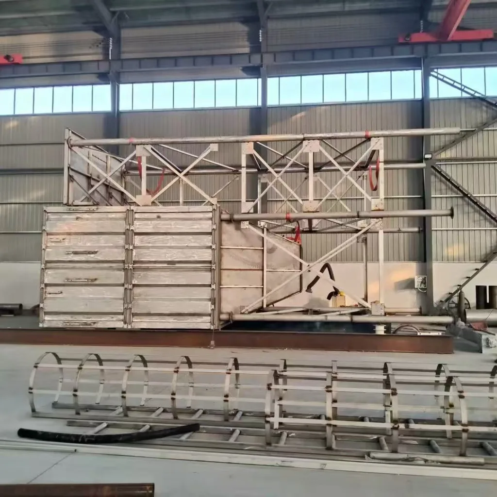
Large perforated sheets are often welded into framed housings or modular sections. Heat introduced near an edge, stiffener, or adjoining wall can cause shrinkage and residual stress. The result may be bowing, local ripples, hole ovality, or movement of hole rows relative to the cleaning system.
A fabrication team can reduce risk by planning the weld sequence, fixturing the assembly, balancing heat input where practical, and inspecting between stages. These are engineering controls rather than a guarantee that distortion disappears. Heavy restraint can sometimes lock in stress; final requirements depend on the plate, material, joint design, and welding procedure.
Flatness and levelness are different measurements. A plate may slope uniformly without being distorted, while a level plate may contain local waves around mounting holes. Inspectors should specify the datum, the measuring grid, and allowable deviation from the reference plane. Check both the entire plate and the local sealing regions if the design requires it.
Weld integrity matters independently of flatness. A cracked, porous, or incomplete joint between the tube sheet and housing can connect the dirty-air chamber to the clean-air compartment. Corrective work should address the weld defect and verify that any additional heating has not altered the hole pattern or seating surfaces.
What Should Be Checked After Welding?
Compare finished dimensions against the approved drawing, not solely against the pre-weld inspection sheet. Recheck representative holes near high-heat zones, plate flatness, connection welds, and alignment to the bag-support and pulse-cleaning assembly. If straightening or repair welding is performed, inspect again afterward.
A shop record is more valuable when it contains actual measurements, locations, inspection dates, drawing revisions, nonconformance decisions, and photographs than when it simply says “tube sheet inspected.” Where nondestructive examination is specified, its method and acceptance criteria should be agreed before fabrication.
Snap-Band Sealing and Filter Cage Fit
How the Bag Collar Creates the Seal
In a common top-load snap-band arrangement, the steel ring inside the bag cuff is compressed for insertion, then allowed to spring outward into the tube sheet hole. The cuff’s bead or groove surrounds the plate edge. Proper compression and full seating create the intended barrier against bypass dust.
A hole that is too large may allow movement or leakage. A hole that is too small, irregular, or rough may prevent the band from opening evenly or may damage the cuff. An incompatible plate thickness can leave the band resting partly above or below its designed groove.
Trial assembly is essential on first articles, unfamiliar replacements, and old baghouses with undocumented modifications. Test the actual production bag-top construction in representative large and small holes. Confirm the cuff seats uniformly and cannot rotate or lift unexpectedly under the supplier’s recommended checks. Do not force a mismatched snap band into service or improvise padding to hide an out-of-specification opening.
The filter cage is part of this fit. A bent cage, incorrect top diameter, unsuitable flange, or wrong length can load the cuff unevenly or create abrasion lower down the bag. Also verify blowpipe alignment before concluding that a damaged bag failed because of its media alone.
Factory Inspection, Installation Checks, and Leak Testing
A sensible inspection program follows the assembly through three stages: before welding, after structural fabrication, and after bags are installed. Each stage answers a different question.
| Stage | Main checks | Record or acceptance evidence |
|---|---|---|
| Pre-assembly | Material, plate thickness, cut-hole pattern, edge finish | Drawing revision and dimensional inspection |
| Post-weld / pre-coating | Flatness, holes near welds, joint condition, geometry | Measurement map, weld records, repairs and reinspection |
| Trial fit / bag installation | Snap-band engagement, cage clearance, bag alignment | Sample fit report and installation sign-off |
| Functional verification | Clean-side dust bypass and leakage locations | Approved leak-test report and corrective-action retest |
After installation, fluorescent tracer powder can help locate a breach. Powder is introduced on the dirty-air side under a controlled procedure, then the clean-air side is examined under UV light following shutdown and safe access. A bright deposit at a bag collar can indicate a sealing path; deposits around a structural seam can point toward the plate or compartment connection.
However, fluorescent powder does not identify why a leak exists by itself. The cause could be incorrect cuff installation, an oversized hole, corrosion, a defective weld, or damage caused during servicing. An illuminated area is a location for investigation, not a manufacturing verdict. The method must be conducted with plant lockout, safe entry, combustible-dust precautions, and suitable tracer compatibility.
Keep leak testing distinct from a complete fabrication audit. A passing tracer test cannot establish hole pitch, plate flatness, or long-term fatigue resistance. And a low differential-pressure reading is not proof of sealing: it can also occur when air finds a bypass route around the filter bags.
What Published Field Cases and Research Teach Us
The following examples are drawn from published third-party industrial investigations, not Omela installations or factory acceptance results. Each finding is specific to its operating conditions and should not be treated as a universal performance guarantee.
Oklahoma Steel Plant: Inconsistent Holes and Repeated Bag Detachment
A published field investigation at an Oklahoma steel plant described filter bags repeatedly disengaging from the tube sheet of a reverse-air baghouse. Technicians measured the holes with precision calipers and found substantial variations across compartments. The existing fiberglass cuffs did not maintain secure seating in the inconsistent openings.
The investigation also identified a malfunctioning rotary airlock that allowed dust to accumulate close to the tube sheet. Dust movement was associated with abrasion and snap-band damage. The reported corrective measures included a more compliant aramid cuff arrangement with a deeper groove and stronger snap band, alongside repair of the airlock. The field report stated that recurring bag detachment was resolved under the site conditions.
Engineering lesson: hole variation can interact with cuff design and operating faults. The reported fix did not prove that every distorted tube sheet can be repaired by choosing softer cuffs; it worked for that site-specific assembly.
Midwestern Power Plant: Tube Sheet Deflection and Bag Contact
A published engineering investigation of a long-bag pulse-jet installation at a Midwestern power generating station identified substantial bag-to-bag contact. The investigators considered tube sheet deflection, bent cages, and imperfect installation possible contributing factors. Their recommendations included clearer installation procedures, bag-wear monitoring, cage assessment, and tube-sheet design review for future units.
Engineering lesson: a tube sheet can affect performance even without a visible sealing leak. Its deflection changes the position of bags and cages, potentially creating mechanical contact. The report also cautioned that contact alone does not necessarily prove premature wear in every design; no quantified post-repair improvement was provided.
California Biomass Power Plant: Corrosion at Tube Sheets and Adjacent Welds
A published field report described severe acidic corrosion in a six-compartment pulse-jet baghouse at a California biomass power plant. Investigators observed damage to clean-air-side walls, lids, and tube sheets. After steelwork repairs, the plant trialed a protective coating in one compartment in 2003.
After seven months, plant personnel reported no visible corrosion in the treated compartment, including areas around seals and weld seams. The treatment was then extended to other compartments. This was a site-reported corrosion-protection result, not a measured hole-tolerance correction or verified improvement in snap-band fit.
Engineering lesson: dimensional acceptance is only the starting point. Process chemistry, condensation, and corrosion protection must be managed so that sealing surfaces and structural joints remain serviceable after commissioning.
Practical Tube Sheet Acceptance Checklist
For a new build, retrofit, or replacement section, request the following before approving the installation:
- Approved interface drawings: hole pattern, tolerances, tube sheet thickness, bag-top design, cage dimensions, and relevant revision numbers.
- Dimensional records: actual hole sizes at defined locations, roundness checks, flatness map, and inspection after final welding or straightening.
- Finish and weld records: edge condition, structural joint checks, defect repairs, coating clearance at seating surfaces, and required weld examination.
- Assembly trial: fit the actual snap-band cuff and cage in representative holes; verify nozzle alignment and clearance.
- Functional closeout: investigate visible dust bypass, perform any specified fluorescent leak test, document repairs, and retest affected sections.
Reject the temptation to use a generic hole tolerance copied from another manufacturer’s brochure. Match the requirements to the selected snap-band system, steel construction, and project drawing. For an existing baghouse, take measurements from the actual plate before ordering replacements, especially where earlier repairs or corrosion may have changed the hole geometry.
Final Engineering Recommendation
The most important question is not whether the tube sheet looks neatly drilled. It is whether the fabricated and installed assembly provides a repeatable, durable seal at every filter opening and across the plate-to-housing joints.
That requires compatible bag-top geometry, measured holes, controlled distortion, clean finished edges, sound welds, and verified installation. Fluorescent leak detection is a valuable final check, but it works best when supported by fabrication records and an understanding of the actual failure mechanism.
FAQ
What Hole Diameter Tolerance Is Required for a Baghouse Tube Sheet?
There is no universal diameter tolerance for every baghouse. The approved bag-top or snap-band design determines the required hole size, roundness, edge finish, and compatible plate thickness. Verify the actual dimensions and trial-fit the specified cuff.
Why Does Tube Sheet Flatness Matter for Filter Bags?
Excessive local distortion may affect hole position, cage alignment, and seating consistency. Flatness should be checked against defined drawing datums after welding and any straightening, rather than judging the plate only by appearance or levelness.
Can Welding Distortion Cause Baghouse Dust Leakage?
Yes. Welding may deform hole geometry or produce defects in the joint separating clean and dirty air. Both conditions can create potential bypass paths. Inspect the finished assembly and recheck it following repair welding.
How Can You Tell Whether a Snap Band Is Properly Sealed?
Check that the cuff is fully seated in the correct tube sheet groove, fits the opening without unexpected movement, and matches plate thickness and cage geometry. Use the supplier’s trial-fit method and investigate any leakage indicated by subsequent tracer testing.
Does a Fluorescent Leak Test Replace Tube Sheet Dimensional Inspection?
No. Fluorescent tracer testing locates possible dust-bypass paths in an installed system, but it cannot verify all hole tolerances, plate flatness, weld geometry, or long-term durability. Both dimensional inspection and appropriate functional testing are needed.
Author

Jessica Ma – Senior Filtration Engineer, Omela Filtration
Jessica Ma is a senior filtration engineer at Omela Filtration, specializing in dust and liquid filtration. With over 15 years of experience, she focuses on optimizing baghouse performance, enhancing filtration efficiency, and developing high-performance solutions for industrial dust collectors and precision liquid filtration applications.