
Key Takeaways
- Select the complete filter system, not just a cartridge length. Start with required flow, liquid properties, solids loading, and retention target before choosing industrial liquid filter cartridges and a matching vessel.
- Standard and high-flow lengths are different product families. Conventional 10″–40″ elements are often around 2.5″ in diameter, while high-flow filter cartridges may be roughly 6″ in diameter and require a dedicated housing and seal arrangement.
- Quantity comes from verified flow per element. Divide maximum operating flow by the supplier’s allowable flow at the chosen micron rating and pressure drop; then check the margin and hydraulic distribution.
- Housing size includes more than vessel diameter. End connections, cartridge seats, operating pressure, lid clearance, drainability, lifting arrangements, and maintenance access must all fit the plant.
- Pressure drop and service life complete the selection. Review the operating causes of premature cartridge plugging and the specific requirements of water and wastewater treatment before approving a design.
Why Cartridge Length Alone Cannot Determine Housing Size
A purchasing inquiry may simply specify “20-inch PP cartridge” or “60-inch high-flow filter.” Neither description is enough to design a reliable liquid filtration system. Two elements with the same nominal length can have different outside diameters, media, end caps, gasket seats, inside-to-outside or outside-to-inside flow paths, and permissible differential pressures.
A housing must hold the cartridge securely while distributing liquid across the intended media surface, preventing bypass and allowing safe changeout. The correct assembly also needs to fit upstream pumps, piping, operating temperature, maximum pressure, and the available maintenance space.
The useful sizing sequence is process duty → filter medium and rating → qualified per-element flow → element quantity and length → housing configuration → pressure and service-life verification. Reversing that sequence—buying a housing by nominal inch size and hoping the flow will be adequate—often creates problems that are expensive to correct later.
What 10″, 20″, 30″, 40″, and 60″ Really Mean
Standard Cartridge Lengths and Their Limits
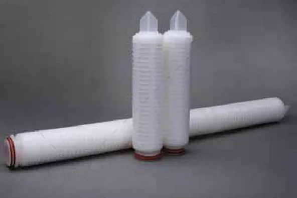
Conventional melt-blown, string-wound, pleated, and membrane cartridges commonly use nominal lengths of 10″, 20″, 30″, and 40″. Some assemblies stack shorter modules; others use one continuous element. A nominal 10″ cartridge may actually measure slightly under 10″, and the precise end configuration changes the required housing dimensions.
Longer standard cartridges offer more potential media area and may reduce the number of parallel elements needed for the same process. But the increase in recommended flow is not necessarily proportional to length. Different media structures, micron ratings, pressure limits, and contaminant loading can alter usable capacity.
High-Flow Elements Are Not Simply Longer Standard Cartridges
A 60″ high-flow element commonly has a much larger diameter and a deep-pleated construction. It may use a proprietary locking connection, internal support basket, or specific flow direction. It cannot be installed in a conventional 2.5″-cartridge vessel simply because both products are called filter cartridges.
Some high-flow families also offer 20″ and 40″ lengths. Therefore, “40-inch” alone does not identify compatibility. Before purchasing replacements, confirm outside diameter, actual overall length, cap geometry, connection code, O-ring material, cartridge support, and flow direction.
| Cartridge category | Common nominal lengths | Housing implication | Main selection caution |
|---|---|---|---|
| Standard small-diameter cartridge | 10″, 20″, 30″, 40″ | Single-round or multi-round vessel | Confirm exact end-cap height and seat type |
| Large-diameter specialty cartridge | Series-dependent | Dedicated support and adapter | Nominal length does not prove interchangeability |
| High-flow pleated cartridge | Often 20″, 40″, 60″; some 80″ | Larger bore, dedicated housing or cradle | Verify rated flow, locking mechanism and service clearance |
Length categories are typical examples, not a universal product standard.
Calculate Cartridge Quantity from Real Operating Flow
Start with Maximum Flow and Required Retention
Record normal flow, maximum simultaneous demand, startup surges, any future expansion, and whether flow must continue during cartridge replacement. Then identify the fluid, temperature, viscosity, solids concentration, target micron rating, and required retention efficiency. Nominal and absolute micron ratings are not directly interchangeable without their test definitions.
Choose a cartridge whose manufacturer publishes a usable flow range at the relevant medium and grade. Prefer a recommended operating flow for service life over an absolute maximum flow figure presented under clean-water conditions.
For a bank of identical elements operating in parallel, the first quantity estimate is:
Required elements = round up [design flow ÷ qualified flow per element].
After that calculation, add appropriate capacity or redundancy based on the actual process risk. Verify that the selected vessel distributes flow adequately among cartridges and that no element is overloaded during normal operation.
Worked Example: 60 m³/h Process Water
Suppose a plant needs 60 m³/h of process water filtration. For the selected retention grade and operating conditions, assume a supplier recommends 6 m³/h per conventional 40″ cartridge. Ten elements meet the arithmetic flow requirement; allowing additional working capacity might lead to a preliminary 12-element housing.
Alternatively, suppose a different, qualified 60″ high-flow model is recommended at 75 m³/h under the same intended duty. One element covers the nominal flow at 80% of that stated rate. That does not prove equivalent retention, dirt capacity, or economic superiority; those claims need comparable data.
| Preliminary option | Verified-flow assumption used in example | Arithmetic cartridge count | Configuration to investigate |
|---|---|---|---|
| Standard 40″ cartridges | 6 m³/h per element | 60 ÷ 6 = 10 | About 12 positions after a project-specific margin |
| High-flow 60″ cartridge | 75 m³/h per element | 60 ÷ 75, rounded up = 1 | Single-element high-flow vessel, subject to full checks |
This is an illustrative sizing exercise, not an Omela product rating or a promise of equal filtration performance.
Calculate Pressure Drop Across the Complete Assembly
A clean cartridge has hydraulic resistance even before solids accumulate. As a filter loads, differential pressure usually increases. A housing adds its own pressure loss through the inlet nozzle, internal passages, cartridge supports, and outlet. Engineers should evaluate:
Total clean assembly ΔP = cartridge/media ΔP + housing/internal-flow ΔP, using consistent flow, temperature, and viscosity assumptions.
The supplier’s empty-housing pressure curve is not the same as the cartridge curve. Likewise, an element’s maximum allowable differential pressure is a mechanical limit, not an approved routine changeout setpoint. Operating pressure, differential pressure, and pressure-vessel design pressure are separate parameters.
Fluid viscosity matters particularly for coolants, syrups, oils, coatings, and concentrated chemicals. Water-based flow charts may substantially understate resistance in more viscous liquids. Any viscosity correction should follow the element supplier’s method and the relevant flow regime; simple scaling is not universally valid for every cartridge and housing.
Check at least two states: clean start-up and expected loaded operation. If the pump cannot maintain process flow as resistance rises, a longer or larger-area cartridge—or additional parallel elements—may be preferable to simply increasing pump pressure.
Match the Housing to the Actual Cartridge and Site
End Connections, Seals, and Mechanical Fit
Double-open-end (DOE), 222, 226, and other single-open-end arrangements use different sealing and retention hardware. In high-flow designs, locking adapters and flow direction can be series-specific. Confirm the exact manufacturer drawing rather than relying on a generic description such as “20-inch stainless housing.”
Select gasket and O-ring materials for the liquid, concentration, cleaning chemicals, temperature, and pressure. Review stainless steel grade, polymer or FRP compatibility, corrosion allowance, pressure design requirements, and drain/vent provisions. Food, beverage, and pharmaceutical service may require documented hygienic design and material compliance.
Vertical, Horizontal, Single-Round, or Multi-Round?
Vertical housings can occupy less floor area but require overhead withdrawal clearance, which becomes significant for long elements. Horizontal high-flow vessels may simplify cartridge withdrawal in low-ceiling rooms, though they need clear working space in front of the closure and adequate support for large wet cartridges.
A single-round housing suits lower flow or one high-capacity element. Multi-round housings support greater flow but introduce more sealing points, internal distribution requirements, and labor during changeout. For processes that cannot stop, parallel housings with proper isolation may allow maintenance while the remaining train operates, if it has sufficient capacity.
Port size also matters. An otherwise correctly sized cartridge bank can be restricted by undersized nozzles or poorly arranged pipework. Specify the vessel for the system’s pressure and hydraulic duty, not just the connection size that matches a nearby pipe.
What Published Industrial Cases Teach Us
The following evidence comes from third-party engineering, manufacturer, and research sources. These are not Omela installations, and their results must not be treated as universal performance guarantees.
European Brewery: Fewer Elements, Less Changeout Work
In a supplier-published European brewery case, the original filtration arrangement included 15 conventional 40″ cartridges and faced high pressure drop during peak flow. A high-flow system was installed before a new RO filtration stage. The supplier reported that maintenance time fell by 90% and described an 80 m³/h design comparison in which one high-flow element corresponded to 18 conventional pleated or 24 depth cartridges under the stated selection assumptions.
The practical lesson is not that one 60″ element always replaces a fixed number of standard filters. Rather, different geometries can change filter quantity, service access, and pressure behavior dramatically at a defined flow.
Beverage Bottling: Horizontal Housing Accessibility
A trade-publication report described a US bottled-water and sports-drink manufacturer adopting high-flow horizontal housings where existing systems occupied valuable production space and required lengthy cartridge changes. It reported that suitable housings could be integrated into the existing installation and that changes taking nearly an hour with earlier systems could be completed in minutes under the new arrangement.
This is evidence for considering service access and closure design during housing selection, not only filtration area. The article’s product-flow examples are supplier claims and should be confirmed for any proposed replacement.
Desalination Plant: Pressure Loss Has an Operating Cost
A peer-reviewed study at Cyprus’s Dhekelia desalination plant examined seven commercially available high-flow cartridge types. The facility supplies approximately 60,000 m³/day of potable water and uses cartridge filtration ahead of reverse osmosis. Researchers reported that their best-performing evaluated cartridge option produced 34% more water with improved quality and that cartridge-filtration production cost could be reduced by up to 39% under the modeled conditions.
This independent comparison highlights why energy consumption, actual filtrate quality, and replacement timing must accompany catalog flow ratings. It does not establish that any specific Omela element would produce those improvements.
A Practical Housing and Cartridge Selection Checklist
- Define duty: Normal/peak flow, liquid chemistry, solids load, viscosity, temperature, required removal grade, and target outlet quality.
- Verify cartridge fit: Nominal and actual length, diameter, end cap, O-ring, locking seat, supports, flow direction, and product-specific pressure limits.
- Size hydraulically: Recommended per-element flow, quantity, clean and loaded ΔP, vessel losses, pump margin, and future expansion.
- Check vessel and access: Design pressure, corrosion resistance, hygienic requirements, vent/drain, isolation, floor space, lid or withdrawal clearance, and lifting needs.
- Review lifecycle cost: Cartridge price, service interval, downtime, labor, disposal, pump energy, and changeout safety.
For an existing system, photograph the installed cartridge, end connection, support arrangement, and housing nameplate. Confirm dimensions before ordering a replacement. When switching technology, ask the supplier for a matched element-and-housing drawing and an application-specific flow/pressure-drop assessment.
Final Engineering Recommendation
The right filter cartridge length is the one that delivers the required retention and operating flow with manageable pressure loss, dirt loading, and maintenance—not necessarily the longest available element. Conventional 10″–40″ cartridges remain practical for many moderate-flow or precision applications, while large-diameter 60″ high-flow elements can reduce element count in suitable higher-flow systems.
Choose the filter first by actual process performance, then engineer the vessel around its precise fit and operating envelope. For a technical quotation, provide the required flow, liquid properties, micron-rating basis, available pressure, preferred element geometry, existing housing dimensions, and service-space restrictions. Those inputs make the final sizing decision measurable rather than a guess based on nominal length.
FAQ
Is a 20-Inch Filter Cartridge Twice the Flow Capacity of a 10-Inch Cartridge?
Not necessarily. Longer cartridges can provide more media area, but recommended flow also depends on media construction, micron rating, viscosity, pressure drop, and the manufacturer’s tested limits. Compare the specific product data rather than assuming a fixed length-to-flow ratio.
Can a 60-Inch High-Flow Cartridge Fit a Standard Multi-Cartridge Housing?
Usually not. Many 60-inch high-flow elements have a larger diameter, different end connections, supports, and flow paths. Use the matching high-flow housing or verify an engineered retrofit using exact drawings and sealing requirements.
How Do I Calculate the Number of Filter Cartridges Needed?
Divide maximum design flow by the qualified per-cartridge flow at the required retention rating and process conditions, then round up. Check housing hydraulics, fouling margin, pump capability, and any redundancy needed for continuous operation.
Does a Larger Filter Housing Always Reduce Pressure Drop?
No. Pressure drop depends on cartridge media, per-element flow, internal housing passages, inlet and outlet connections, viscosity, and solids loading. Compare clean and loaded pressure-loss data for the complete assembly, not vessel diameter alone.
Should I Choose Vertical or Horizontal Housing for 40-Inch and 60-Inch Filters?
Choose based on footprint, overhead or horizontal cartridge-withdrawal clearance, operator handling, isolation, draining, and maintenance access. Long high-flow elements often favor engineered horizontal arrangements, but the correct orientation depends on the specific vessel and site.
Author

Jessica Ma – Senior Filtration Engineer, Omela Filtration
Jessica Ma is a senior filtration engineer at Omela Filtration, specializing in dust and liquid filtration. With over 15 years of experience, she focuses on optimizing baghouse performance, enhancing filtration efficiency, and developing high-performance solutions for industrial dust collectors and precision liquid filtration applications.