There’s a pattern I’ve seen repeat itself across cement plants, steel mills, waste incineration facilities, asphalt operations, and chemical processing sites for the better part of fifteen years: the filter bags fail too early, maintenance costs keep climbing, and when you trace the root cause back, it comes down to one thing. The original specification wasn’t done against the actual operating conditions.
Not against the nameplate temperature. Not against the gas chemistry under full load. Not against what actually happens during startup, upset conditions, or seasonal process changes. Against whatever seemed reasonable at the time, often based on what was previously used, or what was cheapest, or what the equipment supplier originally specified for a different version of the same process.
Wrong material selection is the dominant cause of premature filter bag failure in industrial dust collection. Chemical incompatibility between the gas stream and the filter material causes wear, corrosion, and damage that shortens bag life significantly — and changes in temperature and humidity can alter the chemical composition of the gas stream, creating problems that weren’t apparent at installation. Getting the specification right from the start is the single highest-leverage decision in baghouse performance.
This article walks through the complete selection process: fiber types and their real-world properties, how cleaning mechanism affects the specification, how dust characteristics drive surface treatment choices, and the integrated service process that ensures a correct specification actually translates into correct real-world performance.
Why Filter Bag Material Selection Is More Complex Than It Looks
The Temperature Problem
Operating temperature is the first filter parameter most engineers look at, and it’s an important one. But temperature alone is not sufficient for material selection, and treating it as sufficient is where most specification errors begin.
The distinction that matters is between the continuous operating temperature and the transient peak temperature. Most industrial processes have both. A coal-fired boiler might run at 130°C continuously but reach 160°C during startup. An asphalt mixing plant dryer might run at 120°C under normal production but surge to 200°C when the burner comes up from cold. A waste incinerator might run at 180°C steady-state but exceed 260°C during combustion upsets.
Filter media needs to tolerate the transient peak, not just the continuous rating. A polyester bag rated at 130°C that’s regularly exposed to 160°C startup transients will fail chemically and mechanically well ahead of its rated service life — not because the specification was wrong on average, but because it was wrong at the margins.
The Chemistry Problem
Temperature and chemistry interact in ways that are easy to underestimate. Polyester fiber has excellent properties in dry, moderate-temperature dust collection environments. In the presence of acid and moisture at elevated temperatures — the acid dew point conditions that occur during temperature transitions in high-sulfur flue gas — polyester undergoes hydrolytic degradation. The ester linkages in the polymer backbone are broken by acid attack. The fabric loses tensile strength, becomes brittle, and fails structurally before it reaches its rated service life.
Using the wrong filter material for your application is like wearing a sweater in a snowstorm — it just doesn’t work. Every dust type has its quirks: some are sticky, some are abrasive, some are hygroscopic, some come at high temperatures. If your filter bags aren’t matched to the dust characteristics, operating temperature, or moisture levels, you’re bound to run into problems.
The solution is to start the selection process with a systematic analysis of the actual gas chemistry — not just the temperature — and match the fiber type to the chemistry. This is the core principle behind working condition analysis.
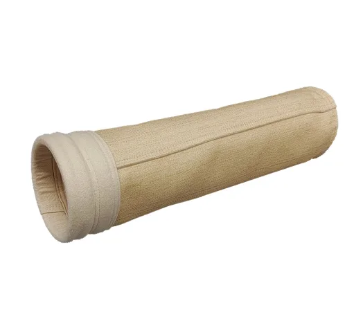
Filter Fiber Types and Their Real-World Properties
Understanding the practical differences between fiber types is the foundation of correct selection. Here’s how the main options compare in real industrial applications:
Polyester (PE) — The Workhorse for Mild Conditions
Continuous rating 130°C, peak 150°C. Good mechanical strength, reasonable cost, good availability in a wide range of fabric weights. Appropriate for dry, non-acidic, moderate-temperature applications: limestone and mineral processing, cement raw material handling, grain and food processing, packaging dust, and some steel industry material handling operations.
The limitation is chemical resistance. In the presence of moisture and acid at elevated temperatures, polyester hydrolyzes. It also has limited resistance to alkali at higher temperatures. For any application with acid gas content and temperatures approaching 130°C, polyester should be evaluated carefully rather than assumed to be appropriate. For a systematic look at understanding dust properties for baghouse and filter bag selection, that article covers the dust chemistry inputs that drive this evaluation.
Acrylic / PAC — Acid Resistance at Moderate Temperature
Continuous rating 130°C, peak 150°C. Similar to polyester in temperature range, but with significantly better hydrolysis resistance and acid resistance. The appropriate choice for applications with acidic gas streams at moderate temperatures: coal mill dust, desulfurization system dust, spray dryer applications, and some chemical processing dust collection where the temperature is within range but the gas chemistry would degrade polyester.
PPS (Polyphenylene Sulfide) — The Coal Power Standard
Continuous rating 160°C, peak 190°C. Excellent acid resistance, excellent hydrolysis resistance, no hydrolyzable bonds. The go-to material for coal-fired boiler applications, high-sulfur flue gas environments, and CFB boiler district heating — anywhere that combines moderate-to-high temperatures with acid gas chemistry. Also appropriate for some metal smelting and chemical processing applications.
The limitation of PPS is oxidation resistance. In environments with elevated oxidizing species — chlorine compounds, NOx, certain chemical processing atmospheres — PPS can degrade faster than expected. This is why PPS, while excellent for coal power, is not always the first choice for hazardous waste incineration where oxidizing halogen species are present.
Aramid / Nomex — High Temperature for Moderate Chemistry
Continuous rating 204°C, peak 240°C. Good mechanical strength at elevated temperatures, reasonable chemical resistance. The standard choice for asphalt mixing plant dust collection, some non-ferrous metal smelting, ceramic and glass production, steel blast furnace gas, and cement kiln applications where the temperature range exceeds PPS capability.
The limitation is hydrolysis resistance at high temperature — in environments with significant moisture content above 180°C, aramid service life can be reduced. Surface treatments can mitigate this, and material grade selection (the difference between standard aramid and precision fine-fiber aramid construction) affects filtration efficiency and dust release performance significantly.
P84 Polyimide — The Bridge to PTFE
Continuous rating 240°C, peak 260°C. Excellent transient high-temperature tolerance. Appropriate for chemically moderate but thermally demanding environments: some cement kiln applications, chemical and metallurgical processing with temperatures that exceed aramid’s range, waste incineration where the chemistry is not as aggressive as full hazardous waste streams.
P84 has a distinctive trilobal fiber cross-section that increases surface area and improves fine dust capture — this gives it better filtration efficiency than round-fiber alternatives at the same fabric weight, which is relevant for applications targeting sub-10 mg/Nm³ emissions at high operating temperatures. For more on our P84 filter bags and their application range, the product page covers the full specification.
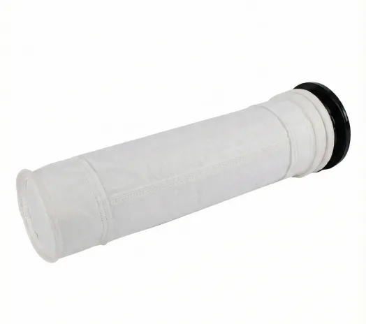
PTFE — The Chemical Resistance Standard
Continuous rating 240°C, peak 260°C. Chemically inert across pH 0–14. Resistant to all acids, alkalis, oxidizing agents, and organic solvents encountered in industrial dust collection. The correct specification for hazardous waste incineration, high-corrosion chemical processing, and any application where gas chemistry is too aggressive for other materials.
PTFE’s inherent low surface energy produces excellent dust release under pulse-jet cleaning — the non-stick surface prevents particle bonding and allows a thin, uniform dust cake to release cleanly. This is why PTFE bags often run at lower pressure drop than comparable non-PTFE alternatives, even in high-dust-loading applications.
The PTFE membrane construction — biaxially-stretched microporous membrane laminated onto a substrate — adds surface filtration capability that captures particles above 99.99% efficiency at the filter surface, enabling sub-5 mg/Nm³ emissions in the most demanding applications. See our full PTFE filter bags product page for the complete technical detail.
Fiberglass — Thermal Stability with Mechanical Limitations
Continuous rating 240°C, peak 260°C. Excellent oxidation resistance, appropriate for high-temperature oxidizing environments where other materials struggle. Used in cement kiln tail, power plant, and some waste incineration applications.
The limitation is mechanical performance — glass fiber is brittle under flex fatigue and doesn’t tolerate aggressive pulse-jet cleaning as well as polymer fiber alternatives. Surface treatment and cleaning system parameter selection are particularly important for fiberglass filter bags.
Quick Reference: Fiber Selection by Application
| Fiber | Continuous Temp | Best For | Avoid When |
|---|---|---|---|
| Polyester (PE) | 130°C | Dry mineral dust, food, packaging | Acid gas, high moisture |
| Acrylic (PAC) | 130°C | Acid gas at moderate temp, spray dryers | High temp (>130°C) |
| PPS | 160°C | Coal power, high-sulfur boilers, CFB | Oxidizing halogen environments |
| Aramid | 204°C | Asphalt plants, non-ferrous smelting | High moisture >180°C |
| P84 | 240°C | High-temp moderate chemistry, cement kilns | Highly oxidizing or corrosive |
| PTFE | 240°C | Hazardous waste, chemical, high-corrosion | Cost-sensitive, mild conditions |
| Fiberglass | 240°C | High-temp oxidizing environments | High flex fatigue (pulse-jet) |
How Cleaning Mechanism Drives Fabric Specification
Material type determines which fibers survive your operating conditions. Cleaning mechanism determines which fabric weight and permeability actually work in your system. These are two separate specification decisions, and both matter.
Different cleaning systems impose fundamentally different mechanical and aerodynamic demands on the filter bag:
| Cleaning Method | Fabric Weight (g/m²) | Air Permeability (L/dm²·min @ 200Pa) |
|---|---|---|
| Shaker cleaning | 300–350 | 400–600 |
| Vibration & reverse air | 350–450 | 250–400 |
| Low-pressure pulse | 400–500 | 150–350 |
| Pulse-jet | 500–650 | 40–150 |
Pulse-jet cleaning uses high-pressure compressed air to collapse the bag inward and release the dust cake. This requires heavier fabric weight — the structural integrity to withstand the mechanical shock of repeated pulses without fatigue failure — and lower permeability, which increases the cleaning pressure differential across the bag surface. A pulse-jet system running a fabric specified for reverse-air cleaning will have poor cleaning efficiency because the pressure differential is distributed through an overly permeable structure.
Conversely, running a heavy pulse-jet fabric in a shaker or reverse-air system increases the fan energy required to maintain the design airflow, because the higher fabric resistance increases system pressure drop. Selecting the correct fabric weight and permeability for your cleaning system is a direct operating cost decision — the compressed air and fan energy consumed by a correctly specified bag versus an incorrectly specified one is measurable over the bag’s service life.
For more on optimizing cleaning parameters, our article on how to clean dust collector filter bags covers the operational detail.
Surface Treatments: Matching the Finish to the Dust
The base fiber and fabric weight get you to the right material for your operating conditions. The surface treatment gets you to the right performance for your specific dust characteristics. This is the layer of the specification that’s most often overlooked — and it has a significant effect on both filtration efficiency and service life.
The table below summarizes the recommended surface treatments by dust characteristic:
| Dust Characteristic | Singeing | Calendering | Silicone Treatment | Water & Oil Repellent | Chemical Protection | PTFE Impregnation | Fine Fiber |
|---|---|---|---|---|---|---|---|
| Free-flowing | ✓ | ||||||
| Cohesive / caking | ✓ | ||||||
| Corrosive | ✓ | ✓ | |||||
| Moist / humid | ✓ | ✓ | |||||
| Sticky / adhesive | ✓ | ✓ | ✓ | ✓ | |||
| Acid / alkaline | ✓ | ||||||
| Ultra-fine particles | ✓ |
Singeing burns fine fiber ends off the filter surface to create a smooth, consistent surface that releases free-flowing dust cleanly and resists pinholes from abrasive particles.
Calendering heat-presses the filter surface to close surface pores, creating a smooth face that releases cohesive or sticky dusts more effectively and improves dust cake uniformity.
Silicone treatment reduces surface energy and improves chemical resistance, appropriate for corrosive dust environments at moderate temperature ranges.
Water and oil repellent treatment prevents moisture and oil mist from wetting the filter surface, which would cause dust cake blinding. Critical for humid environments and applications with oil-bearing aerosols.
Chemical protection / PTFE impregnation provides acid and alkali resistance by coating the fiber surface with a chemically inert layer. Standard for acid gas environments across PPS, aramid, and fiberglass substrates.
Fine fiber / superfine fiber construction intercepts ultra-fine particles at the filter surface rather than through depth filtration. This is what enables sub-5 mg/Nm³ emissions in demanding applications, and it’s the engineering basis for the performance difference between standard needle felt and precision-engineered filter media.
The Six-Step Integrated Service Process
Selecting the right material is necessary — but it isn’t sufficient. A correctly specified filter bag that’s improperly installed, installed in a poorly maintained system, or never verified after installation will underperform relative to its specification. The gap between “correct specification” and “correct real-world performance” is closed by a systematic service process.
At Omela Filtration, our integrated support covers six stages:
Step 1 — Working Condition Analysis
Before any product recommendation is made, we review the actual operating data: gas volume (m³/h), temperature profile (continuous and peak), gas chemistry (acid species, moisture content, oxygen content, oxidizing compounds), dust loading and particle size distribution, cleaning system type and parameters, and current bag performance history if available.
This review determines which fiber type, fabric weight, and surface treatment combination is appropriate — not what’s cheapest, not what was previously used, but what’s engineered for the specific conditions. Five factors that influence filter bag service life are all addressed at this stage.
Step 2 — Filter Bag Disassembly and Installation
Correct installation is as important as correct specification. Installation errors — snap bands not properly seated, bags kinked during installation, damaged cages reused with new bags, incorrect orientation — create failure modes that emerge within months of installation and are routinely misattributed to material quality rather than installation error.
Incorrect installation — including slack snap bands, misaligned cages, or crimped seams — can result in leakage, shortened filter life, and sealing issues. Our installation service covers removal of old bags and cages, cage inspection and replacement recommendation, bag installation with dimensional verification, and snap-band seating check. For reference, our filter bag and cage installation guide covers the technical requirements.
Step 3 — Dust Collector Maintenance
A new set of filter bags installed in a poorly maintained baghouse system will underperform. Hopper discharge blockages cause dust re-entrainment that abrades bag bottoms. Worn pulse valves deliver inconsistent cleaning pulses that leave bags partially loaded between cycles. Corroded or bent cage wires create abrasion points that wear through bag fabric over months of operation.
Pre-installation system inspection identifies maintenance requirements that would otherwise shorten the new bags’ service life — issues that have nothing to do with the bags themselves but affect their performance once installed.
Step 4 — Fluorescent Powder Leak Testing
After installation, fluorescent powder (tracer powder) leak testing is the most reliable method for verifying that bags are correctly seated, seams are intact, and no bypass paths exist through the tubesheet or bag closures. Tracer powder is introduced into the gas stream; any powder detected on the clean-air side indicates a leak path that needs to be found and corrected before the system is returned to service.
This step is particularly important in applications with stringent emission compliance requirements — waste incineration, chemical processing, ultra-low emission zones — where a single leaking bag can cause regulatory exceedances that are attributed to the filter system rather than to an installation defect. We include fluorescent powder leak testing as a standard post-installation verification step for these applications.
Step 5 — Failure Analysis and After-Sales Tracking
When bags fail ahead of schedule, the failure mode carries information about what’s happening in the system. Acid attack produces characteristic fiber degradation patterns. Thermal overexposure produces different visual and mechanical signatures. Abrasion damage concentrates at specific locations that identify system design or operation issues. Blinding patterns indicate cleaning system problems or dust property changes.
Systematic failure analysis identifies the root cause and informs the corrective action — whether that’s a material specification change, a cleaning system adjustment, a system design modification, or an operational change upstream of the baghouse. Treating premature failure as a product quality issue without investigating the root cause leads to repeated failures with successive bag sets.
Step 6 — Dust Collector Renovation
In some cases, the baghouse system itself is the limiting factor — a system designed for 30 mg/Nm³ emissions that now needs to achieve 10 mg/Nm³, or a system whose airflow design creates localized high-velocity zones that cause accelerated bag wear, or a system whose cleaning mechanism is no longer performing adequately after years of wear.
Dust collector renovation — which may include airflow distribution modification, cleaning system upgrade, hopper design adjustment, or cell plate repair — addresses these system-level constraints that filter bag specification alone cannot overcome. Our renovation service covers system inspection, performance baseline measurement, engineering review, and implementation, with post-renovation emission verification to confirm the target performance level is achieved.
Putting It Together: From Process Data to Correct Specification
The selection process, done correctly, follows this sequence:
First, document the actual operating conditions — temperature profile including transient peaks, gas chemistry including acid species and moisture, dust characteristics including particle size and chemical properties, and cleaning system type and current parameters.
Second, select the fiber type that provides the necessary temperature rating with margin above the transient peak, and the chemical resistance profile that matches the gas chemistry. Refer to the fiber comparison table above.
Third, select the fabric weight and permeability appropriate for the cleaning mechanism. Match the specification to how the system actually cleans, not to a standard product.
Fourth, select the surface treatment based on the dust characteristics. Free-flowing dry mineral dust has different finishing requirements than sticky, humid, or acidic dust.
Fifth, verify cage compatibility — diameter, length, closure type — to ensure the new bags fit the existing cage configuration. Dimensional errors discovered after delivery create delays and replacement costs.
Finally, verify the installation and system condition before putting the new bags into service.
This process is what 5 factors for choosing the right dust collector filter media material covers from an engineering selection perspective. For guidance on measuring your existing system before replacement, our article on how to measure dust collector filter bags and cages for a perfect fit walks through the dimensional verification process.
To discuss your specific application or request a working condition analysis, visit our filtration services page or contact our engineering team directly.
Frequently Asked Questions
How do I know which filter bag material is right for my application?
The starting point is always the operating conditions — not the bag catalog. The key inputs are: continuous operating temperature and peak transient temperature, gas chemistry (acid species, moisture content, oxidizing compounds), dust characteristics (particle size, moisture content, stickiness, chemical properties), and cleaning mechanism type. These four parameters together determine which fiber type and surface treatment are appropriate. Working condition analysis — either done internally using the framework in this article or with engineering support — is the process that translates operating data into a correct material specification.
Why do filter bags sometimes fail within months of installation?
Incorrect filter media selection, installation errors, and system design issues are the three most common causes of early filter bag failure. Installation errors — snap bands not seated, cages damaged or misaligned, bags kinked during installation — create failure modes that appear within months and are routinely misattributed to material quality. A pre-installation system inspection and post-installation leak test eliminates most of these failure modes before they develop into operational problems.
What is the difference between PTFE membrane filter bags and PTFE impregnated filter bags?
PTFE impregnation treats the fiber surface of a conventional needle-felt bag with a PTFE coating to improve chemical resistance and surface release. This is a surface treatment applied to an existing fiber substrate — it improves performance but doesn’t change the fundamental filtration mechanism (depth filtration through the fabric). A PTFE membrane filter bag laminates a biaxially-stretched microporous PTFE membrane onto the filter surface, creating surface filtration at the membrane rather than depth filtration through the felt. This is a fundamentally different filtration mechanism — one that enables filtration efficiency above 99.99% on fine particles, sub-5 mg/Nm³ emission performance, and more consistent pressure drop over the bag’s service life. The two are appropriate for different applications and should not be treated as equivalent options.
How does cleaning mechanism affect filter bag selection?
The cleaning mechanism determines the mechanical and aerodynamic demands on the filter bag, which drives fabric weight and air permeability requirements. Pulse-jet cleaning requires heavier fabric (500–650 g/m²) and lower permeability (40–150 L/dm²·min at 200 Pa) to withstand repeated high-pressure pulses and maintain structural integrity under flex fatigue. Shaker or reverse-air cleaning systems use lighter fabric weights (300–450 g/m²) and higher permeability because the cleaning mechanism is gentler and airflow resistance needs to be minimized. Installing a heavy pulse-jet fabric in a reverse-air system raises operating energy costs unnecessarily; installing a light reverse-air fabric in a pulse-jet system accelerates mechanical failure.
What is fluorescent powder leak testing and when should it be done?
Fluorescent powder (tracer powder) leak testing introduces visible tracer particles into the gas stream upstream of the baghouse. Any tracer powder detected on the clean-air side — at the baghouse outlet, on the clean-air surfaces, or through UV lamp inspection — identifies a leak path: an unseated bag, a seam failure, a tubesheet defect, or an installation error. It should be done after every new bag installation or major replacement project, and is particularly important in applications with strict emission compliance requirements where a single leaking bag can cause regulatory exceedances. The test takes a few hours and provides definitive installation verification that emission measurement alone cannot offer — because emission testing averages across the entire filter area and may not detect a single leaking bag until it becomes a significant defect.
How can I extend the service life of my filter bags?
The highest-leverage actions are: correct initial material specification matched to actual operating conditions (not nominal conditions); correct cleaning system parameters — pulse pressure, cycle frequency, and timing matched to differential pressure feedback rather than fixed timers; regular cage inspection to identify and replace bent, corroded, or damaged cage wires before they create abrasion failure modes in new bags; proper installation verification through fluorescent powder leak testing; and systematic failure analysis when bags do fail ahead of schedule, to identify the root cause rather than simply replacing like for like. Our article on top 5 factors influencing the service life of dust filter bags covers each of these in detail.
Author
Jessica Ma – Senior Filtration Engineer, Omela Filtration
Jessica Ma is a senior filtration engineer at Omela Filtration, specializing in dust and liquid filtration. With over 15 years of experience, she focuses on optimizing baghouse performance, enhancing filtration efficiency, and developing high-performance solutions for industrial dust collectors and precision liquid filtration applications.