Filter bag selection gets most of the engineering attention in baghouse dust collection. It makes sense — the filter media is the core functional element, and getting the material specification wrong guarantees failure regardless of everything else. But in 15 years of working on baghouse installations across cement, power, steel, chemical, and waste-to-energy applications, I’ve seen more bag changes fail because of how the bags were installed and commissioned than because of what media was specified.
A perfectly specified PTFE membrane filter bag installed over a deformed cage, seated in a corroded tube sheet, in a system with leaking pulse valves and no pre-coating, will produce disappointing emission results and shortened service life — and the plant will blame the bag. The bag was fine. Everything around it wasn’t.
This guide covers the complete sequence from receiving filter bags through storage, pre-installation inspection, installation procedure, cage and blow pipe alignment, pre-coating, fluorescent powder leak detection, startup protocol, and ongoing maintenance. Every step exists for an engineering reason. Skipping any one of them introduces a specific failure mode that will show up in the emission data or in premature bag replacement — usually both.
Before Installation: Storage and Pre-Inspection
Most filter bag damage happens before the bags are ever installed, and it’s almost always preventable.
Storage requirements
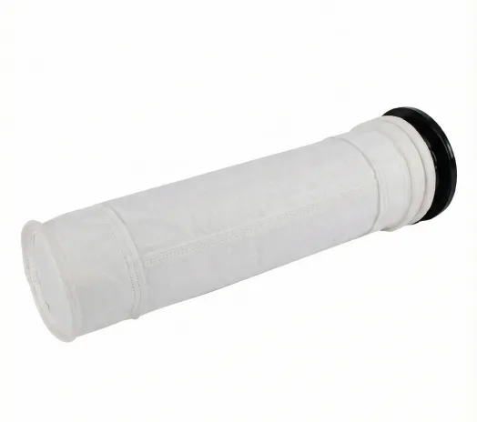
Dust filter bags should remain in their original packaging until the day of installation. The packaging is designed to protect both the filter media and any PTFE membrane lamination from physical damage, UV degradation, and moisture absorption. Bags stored outside their packaging — leaning against walls, stacked on floors, exposed to sunlight or rain on an outdoor staging area — accumulate damage that’s invisible at the time but produces measurable performance problems after installation.
The specific storage conditions that matter: keep bags away from heat sources and open flame (the packaging is combustible, and some filter media are thermoplastic); store upright with pallet separation between layers, not stacked more than four layers high to avoid compression damage to the lower boxes; avoid storage temperatures above 65°C; and keep the storage area dry with no direct sunlight exposure. Inspect every individual bag before installation — any bag showing visible damage to the media surface, membrane delamination, collar deformation, or stitching defects should be rejected.
For PTFE membrane filter bags specifically, the bags ship with a protective sleeve over the membrane surface. This sleeve serves a critical function: it prevents the membrane from being scratched or punctured during handling and the insertion process through the tube sheet hole. The protective sleeve stays on the bag during insertion into the tube sheet and is only removed after the bag is seated. We’ll come back to this in the installation sequence.
Pre-installation equipment inspection
Before a single bag goes into the baghouse, the receiving infrastructure needs to be verified. This step gets skipped more than any other — plants are eager to get the new bags in and the system back online, and the pre-installation inspection feels like it’s slowing things down. It isn’t. It’s preventing the repeat failure that will slow things down much more.
The tube sheet inspection covers several specific items. Every tube sheet hole must be checked for correct dimensions — the bag collar and snap ring need to seat properly in the hole, and dimensional mismatch caused by corrosion buildup or manufacturing tolerances creates bypass leakage that no amount of bag specification improvement can fix. The tube sheet surface around each hole must be smooth and flat, without raised weld spatter, corrosion pitting, or deformation from previous bag removals. The tube sheet welds must be continuous and leak-free — any crack or gap in a tube sheet weld is a direct path for unfiltered gas to reach the clean-air plenum. Any structural damage or corrosion must be repaired before new bags are installed. Welding is prohibited after bags are in place.
The collector interior needs to be cleaned. This means the ductwork upstream of the baghouse, the blow pipe manifolds, and the hopper — residual dust, welding debris, bolts, tools, or any other foreign objects left inside the collector will end up impacting the filter bags or clogging the cleaning system after startup. The blow pipe system needs a cleaning cycle run to purge accumulated dust from the compressed air manifold.
Filter cages must be inspected individually before use. Check for dimensional accuracy — the cage must match the bag specification exactly. Check for deformation, bowing, broken support rings, burrs, and weld spatter at the ring-to-vertical wire joints. Check for corrosion that has roughened the surface. Any cage with quality issues must be replaced, not straightened or reused. A deformed cage inside an otherwise perfect filter bag will cause the bag to flex unevenly during cleaning pulses, creating abrasion wear at the contact points between the bag and the cage. This is one of the most common causes of premature mechanical bag failure, and it’s entirely avoidable.
Check the collector interior walls for sharp edges, protruding screws, and structural protrusions in the bag installation zone — any of these can scratch or tear the bag during insertion or cause ongoing abrasion damage as the bag flexes during operation.
The Installation Procedure: Step by Step
The installation sequence matters because each step builds on the previous one. Doing them out of order or skipping steps introduces specific risks.
Membrane bag installation with protective sleeve
For PTFE membrane bags, the protective sleeve must be used during insertion. Open the packaging box with the red tape, remove the protective sleeve and instruction manual. The sleeve’s purpose is to prevent the tube sheet hole edges from scratching the membrane surface as the bag passes through — a scratch through the PTFE membrane creates a permanent leak path that defeats the entire purpose of membrane lamination.
Place the protective sleeve into the tube sheet hole first, with the metal ring resting on the top of the tube sheet opening. Feed the bag bottom through the protective sleeve, then lower the entire bag body and length through the hole slowly, guiding it by hand at the open end. Position the bag so the seam line faces the inlet airflow direction. For flat bags, orient the bag bottom’s long axis parallel to the tube sheet long axis direction.
Once the bag body is through, grip the protective sleeve’s metal ring, pull the sleeve out through the adjacent tube sheet hole, and set it aside for the next bag installation. Then seat the bag collar: lift the bag mouth up from the tube sheet hole, compress the spring expansion ring at the bag collar into a C-shape with both hands, press the C-shaped collar tightly against the tube sheet hole edge, and slowly release the expansion ring. The ring must expand into the tube sheet hole groove, seating flush against the groove surface 360 degrees around the circumference.
Verification: grip the tube sheet firmly above the installed bag and attempt to rotate it. If the bag rotates, the collar is not fully seated — the snap ring has not engaged the tube sheet groove completely. This means there’s a gap between the bag collar and the tube sheet that will allow bypass leakage. Do not proceed to the next bag. Remove the bag, inspect the snap ring and the tube sheet groove, identify the cause of the incomplete seating, and reinstall. A rubber mallet can be used gently to help seat the snap ring if the tube sheet groove has minor dimensional irregularities, but significant mismatches require reporting to the tube sheet inspection team. For non-membrane bags, the installation procedure is the same except the protective sleeve step is omitted.
Cage installation
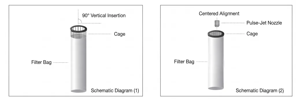
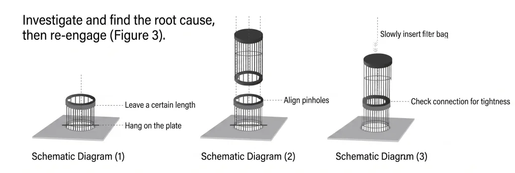
After the bag is seated, lower the filter cage into the bag carefully. The cage must enter the bag at 90 degrees to the tube sheet — vertically, not at an angle. Guide it gently to the bag bottom without forcing. If a cage placed inside a bag doesn’t drop freely to the bottom under its own weight, something is wrong — the cage may be oversized for the bag, the bag may not be seated correctly in the tube sheet, or there may be an obstruction. Do not force it. Investigate and resolve the interference before proceeding.
The cage must hang vertically once installed. A cage that isn’t perpendicular to the tube sheet will cause the bag to lean against adjacent bags or against the collector wall. The resulting contact creates abrasion wear at the contact points and can also cause the leaning bag to collide with the separator plate between compartments, producing mechanical damage to both the bag and the collector structure.
For multi-section cages (typically used for bags longer than 3 meters), the upper, middle, and lower cage sections need two-person installation. One person feeds the lower section through the bag; the other aligns the pin connection between sections. Check that the pin connections between sections are secure and properly engaged. Lower the assembled cage framework slowly into the bag — never allow it to free-fall or impact the bag bottom, as this can deform the bag collar and break the tube sheet seal.
Blow pipe alignment
For pulse-jet cleaning systems, the blow pipe nozzle must be centered precisely above each bag mouth. Misaligned blow pipes deliver cleaning pulses off-center, which creates uneven cleaning — one side of the bag receives the full pulse energy while the other side doesn’t clean properly. Over time, the uncleaned side develops a progressively thicker dust cake that increases local differential pressure and causes the bag to flex asymmetrically during cleaning, accelerating mechanical wear.
Secure the blow pipe firmly to prevent vibration-induced displacement during operation. Blow pipe movement from pulse shock can shift the nozzle position over time, gradually degrading cleaning performance across an entire compartment without any visible indication until pressure drop or emission data reveals the problem.
Post-Installation: Pre-Coating and Leak Detection
These two steps are the difference between a successful commissioning and a first-month emission exceedance. Both are routinely skipped under production pressure. Both should be treated as non-negotiable.
Pre-coating
Pre-coating deposits a thin protective layer of calcium hydroxide (hydrated lime) powder on the surface of the fresh filter bags before the first exposure to process dust. The recommended application rate is approximately 0.25 kg/m² of total bag surface area, distributed evenly across all compartments.
The engineering reason for pre-coating is specific to the initial startup period. When a new bag first encounters the process gas stream, the finest and most penetrating dust particles — including sticky, hygroscopic, or chemically reactive fines — reach the bag surface before a stable protective dust cake has formed. Without pre-coating, these first-contact particles can penetrate into the fiber structure of depth-filtration media and partially blind the bag before the natural dust cake develops. For PTFE membrane bags, the first-contact particles can adhere to the membrane surface with greater tenacity than they would to an established dust cake surface, causing higher-than-expected initial pressure drop.
The pre-coating procedure: close all cleaning system components — pulse valves, reverse air valves, and all control instruments. Open the inlet and outlet dampers for all compartments. Open the feeding port at the baghouse flue gas inlet. Start the main ID fan and bring the system to operating airflow. Feed the pre-coating material slowly and evenly through the inlet feeding port. When feeding is complete, close the main fan gradually. The pre-coating layer should be applied within 24 hours before the first startup — if the system has not started within 24 hours of pre-coating, the pre-coat must be reapplied.
Critical: never introduce low-temperature, high-humidity flue gas directly into a pre-coated baghouse. The moisture will wet the lime pre-coat and turn it into a calcium hydroxide paste that cement-blinds the bags permanently. The boiler or process must be brought to normal operating temperature before the baghouse damper is opened to direct process gas through the filter bags. If the process burns heavy oil or diesel during startup, the flue gas must not be directed through the baghouse until the system transitions to normal fuel — the hydrocarbon content in startup fuel exhaust will contaminate the pre-coating layer and the bag surface.

For detailed product information on pre-coating materials, see our baghouse lime pre-coating powder page.
Fluorescent powder leak detection
After all bags and cages are installed and before startup, a fluorescent tracer powder leak detection test should be performed on every compartment. This is the only reliable method to verify that every bag collar is fully sealed, every tube sheet weld is intact, and every access door gasket is providing a complete seal — before the system goes online and any leakage starts contributing to stack emissions.
The procedure: start the main ID fan and close the cleaning system. Bring the airflow to 50–70% of rated capacity while keeping the cleaning system off — this creates the pressure differential needed to pull the tracer powder through any leak points. Introduce a measured quantity of fluorescent tracer powder through the inspection port on the inlet side of the baghouse. The application rate is 3.0–5.0 g/m² of total bag surface area (varies between membrane and non-membrane bags). After the powder has been fully introduced, run the fan for 10–15 additional minutes to allow the tracer to migrate through any leak paths.
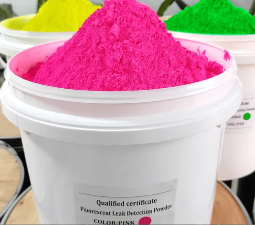
Shut down the fan, open the clean-air plenum access covers, and inspect all tube sheet surfaces, weld seams, bag collar seating areas, and access door gasket lines under ultraviolet light in darkened conditions. Fluorescent traces at any location indicate a specific leak that must be repaired or re-seated before the system returns to service. Document every leak location. After repair, if a second leak detection pass is needed, use a different color fluorescent powder to distinguish new results from the first pass residue.
Night-time inspection produces the best results because ambient light reduction makes fluorescent traces easier to identify. If daytime inspection is necessary, use light-blocking covers or enclosures around the plenum inspection area to reduce ambient light interference.
Startup Protocol: the First 24 Hours
The startup sequence protects the investment made in new bags, new cages, pre-coating, and leak detection. Getting it wrong can undo all of that work in the first shift.
Before directing process gas to the baghouse, verify: bag installation completeness and integrity, pre-coating application (within the preceding 24 hours), no moisture accumulation on the bags or tube sheet, no condensation (plate caking) on internal surfaces, and fluorescent leak detection with all leaks resolved.
During the initial load-on period, start the main ID fan at low load (30–40% of rated capacity) and gradually increase to full load over 1–2 hours. This gradual ramp allows the bag surface to accumulate a protective initial dust layer progressively — rather than hitting the fresh bags with the full dust load from the start, which risks overloading the pre-coat layer and causing premature blinding at the surface. Never go to full fan load immediately on a fresh bag installation. The first-hour dust accumulation on the bag surface is the single most important period in the bag’s entire service life — the quality of the initial dust cake determines the bag’s filtration performance and pressure drop behavior for years to come.
Check the pulse-jet cleaning system and reverse air mechanisms for correct operation during the initial run period. Monitor differential pressure across each compartment during the ramp-up — any compartment showing significantly different behavior from the others warrants investigation.
Gas temperature at the baghouse inlet must stay below the rated continuous temperature of the installed filter media at all times — and must stay above the acid or moisture dewpoint temperature by at least 20°C to prevent condensation on the filter media surface. Operating between these two temperature limits is the operating envelope that determines bag service life. Every excursion outside this envelope — high or low — consumes a portion of the bag’s remaining service life that cannot be recovered.
Ongoing Maintenance: What to Check and When
A baghouse that has been correctly installed and commissioned will perform reliably for years — if it’s maintained. The maintenance requirements are not complex, but they’re non-negotiable.
Compressed air system
The compressed air supply for pulse-jet cleaning must be clean, dry, and oil-free. Contaminated compressed air — containing moisture, compressor oil, or particulate — causes three specific problems: moisture in the pulse air can wet the bag surface from the clean side, creating internal paste-blinding; oil contamination creates sticky spots on the bag surface that capture dust permanently; and particulate in the pulse air can damage the PTFE membrane surface. Compressed air quality must meet ISO 8573-1 (equivalent to GB-T1327791).
Substandard compressed air pressure causes pulse valve failures — valves that don’t open and close correctly under insufficient pressure will either fail to clean (remaining closed) or leak continuously (failing to close completely). Leaking pulse valves bleed pressure from the manifold, reducing cleaning pulse energy across the entire compartment. The result is progressive blinding of bags that are receiving inadequate cleaning energy while appearing to receive cleaning pulses on the control system.
Compressed air system maintenance includes: regular drainage of moisture from the air receiver and distribution manifold, regular servicing of inline filters, regular inspection and maintenance of pressure regulators and gauges, and periodic inspection and replacement of electromagnetic pulse valve diaphragms.
Baghouse daily maintenance checklist
After each process stop, keep the pulse-jet cleaning system running for 2–3 additional minutes before shutting down to remove residual dust from the bag surfaces. Monitor differential pressure trends across compartments — a gradual increase that doesn’t respond to cleaning indicates either a cleaning system problem, media blinding, or hopper buildup. A sudden spike indicates a process upset, a failed bag, or ash bridging in the hopper.
Inlet gas temperature must never exceed the media peak temperature rating. It must simultaneously stay more than 20°C above the acid dewpoint to prevent surface condensation and corrosion. Periodically inspect the hopper discharge and ash removal system — accumulated ash in the hopper reduces the bag bottom clearance, increases local gas velocity, and causes abrasive wear on the lower bag sections. This is a common failure mode that looks like a media problem but is actually a housekeeping problem.
During each scheduled maintenance stop, inspect the internal surfaces of the ductwork, tube sheet, bags, and cages for evidence of dust leakage. A horizontal dust ring on a cage support wire is a diagnostic indicator that the bag above that point has a hole or membrane breach — the dust settles on the cage wire below the breach location. Document every bag replacement with a position map showing which bags were replaced and when — this creates a diagnostic record that reveals patterns of position-specific failures caused by localized gas flow, temperature, or structural issues.
Collector design factors that affect bag life
Four structural aspects of the baghouse design directly influence filter bag service life beyond the media specification itself: blow pipe alignment and angular positioning relative to the bag mouths; tube sheet levelness and hole-to-hole dimensional consistency; inlet distribution baffle geometry and the resulting gas velocity distribution across the bag rows; and cleaning system pressure and timing consistency across compartments.
If the baghouse was designed and constructed to the applicable national standards and codes, these factors should be within tolerance. If the construction quality is poor — unlevel tube sheets, misaligned blow pipes, no inlet distribution — the best filter bag specification in the world will produce shorter-than-expected service life because the bags are operating in conditions the media was never designed to handle.
Cold climate and sulfur-bearing gas considerations
In cold climates or for applications processing sulfur-bearing flue gas, the shutdown and idle period management is critically important. After the process stops and the baghouse is taken offline, run the pulse-jet cleaning system to remove the dust cake from the bag surfaces while gas flow is still present to carry the dislodged dust to the hopper. Then keep the ID fan running for 2 hours after the process stops to evacuate residual flue gas from inside the baghouse and ductwork.
The reason for this is condensation prevention. Residual sulfur-bearing flue gas trapped inside a cooling baghouse will reach the acid dewpoint as the temperature drops, depositing sulfuric acid condensate on the bag surfaces, tube sheet, and cage surfaces. This acid condensate attacks the filter media and corrodes the structural steel. In cold climates, moisture condensation — even without acid — wets the residual dust cake and produces paste-blinding when the system restarts.
For systems that operate intermittently or that shut down overnight in cold weather, sealing the baghouse and using a hot air circulation system to maintain the internal temperature above the dewpoint during idle periods is the correct engineering response. The alternative — allowing the system to cool to ambient and then restarting through the condensation temperature range every day — will destroy the bags in a fraction of their normal service life.
Author
Jessica Ma – Senior Filtration Engineer, Omela Filtration
Jessica Ma is a senior filtration engineer at Omela Filtration, specializing in dust and liquid filtration. With over 15 years of experience, she focuses on optimizing baghouse performance, enhancing filtration efficiency, and developing high-performance solutions for industrial dust collectors and precision liquid filtration applications.